Omron Robot
Note: In addition to the setup information below, refer to the video lesson (in English) on the Visual Components Academy.
About the plugin
The Omron Robot plugin allows you to connect to an Omron robot controller during simulation and exchange data. For example, a program running in a virtual or physical Omron controller can drive the joints of an Omron robot in a simulation, read data from sensors, and set outputs for picking and placing of products.
The plugin is associated with the Connectivity feature of Visual Components Premium 4.10 and can connect to one or more Omron robot controllers. The simplified workflow is as follows:
- Add server.
- Connect to the server.
- Map variables.
- Run the simulation.
Terminology
- ACE (Automated Control Environment) – Omron technology used for communicating with their controllers. ACE software is used to program robots and the ACE API is used by the plugin for communicating with an emulated or physical Omron controller.
- API (Application Program Interface).
- DLL (Dynamic-Link Library).
- IO (Input/Output).
Read and Write Support
Read and Write table
| Type | Read | Write | Notes |
| Robot controller digital inputs and outputs |
Yes |
Yes | Signals |
| Current joint values from any robot of the connected controller |
Yes |
No | |
| Current world, base and tool position of robot | Yes | No | XYZ and yaw, pitch and roll |
Requirements
The connection requires Visual Components Premium 4.10 and the ACE API to be installed on the same computer. The Omron Robot plugin supports version 4.x of ACE API.
See the following options:
Note: ACE 4.x is available from your regional Omron office or website.
Option 1: Visual Components Premium 4.10 + ACE 4.x software.
When adding a server for the Omron Robot plugin, an indicator appears if the libraries (DLL) from the ACE API are found on the machine.
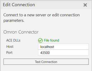
The default path is C:\Program Files\OMRON\ACE 4.X\bin\Modules\Ace and this path can be modified by editing the VisualComponents.Connectivity.Omron.dll.config file found in your Visual Components program files.
Setup
Note: In addition to the setup information below, refer to the video lesson (in English) on the Visual Components Academy.
- Check that your host machine meets the requirements.
- Access the Omron robot controller.
- The plugin connects to the robot controller, so the virtual or physical robot controller should be accessible via a direct network connection (IP address). For example, it is enough to have a project running in ACE software using the Open in Emulation Mode option for the robot.
- In Visual Components Premium 4.10, add a new server with the plugin and connect to the controller.
- If you are using a virtual robot controller running in ACE software, use localhost for the IP address. Otherwise, use the IP address specified for the controller.
- In both cases, use Port 43500 for the first controller in your project. If you need to connect to multiple controllers, use Port 43600 for the second controller connection, 43700 for the third, etc.
- Check the IP address of the targeted controller and the Application Manager for your Omron project.
- Make sure you can ping the IP addresses from the host machine and verify the connection type in your project, for example Ethernet connection via a hub.
- Remember to use the ACE port specification for the connection, and not a port for example specified by the Application Manager.
- Map the variables.
- For example, map the VALUE property of each degree of freedom (DOF)/Joint of the robot component to a joint of the corresponding mechanical unit in the controller. This way, the controller drives the robot in the 3D world.
- For simulating actions such as grasp/release, map the outputs of the robot component for those actions to the I/O of the controller you will use for those actions.
- Run the simulation.
- Simulate to start the exchange of data. Note that in the Connected Variables panel, the Prepared value column can be used to set values for testing.
Capabilities
You can verify the capabilities of the Omron Robot plugin and subsequent server connections in the Properties panel.
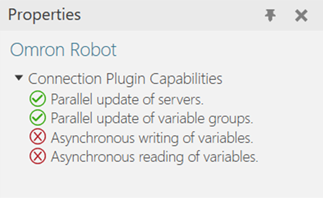
Plugin
- In the Connectivity Configuration panel, select Omron Robot.
- In the Properties panel, expand Connection Plugin Capabilities.
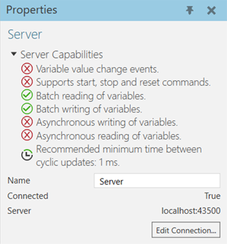
Server
- In the Connectivity Configuration panel, expand Omron Robot, and then select an active server connection.
- In the Properties panel, expand Server Capabilities.
Connection Settings
An Omron Robot plugin connection requires an Omron Robot controller to have an IP address and to be running an ACE server instance. Each connection in Visual Components is a client to the ACE server.
Error handling
- If the requirements are not met (e.g. ACE API is not installed), attempting to add a server will fail.
- If the connection to the controller is lost, the exchange of data will stop. The plugin expects an event to be received from the controller in such cases. If the event is not received, you might need to manually disconnect Visual Components from the controller, and then attempt to reconnect to verify the connection is lost.
- Some inputs and outputs might be reserved for use in your Omron project, for example motor power on and off and emergency stop. Be aware of how signals are used in your Omron project when attempting to write those signals during simulation.
Limitations
- Event-based update mode works only for simulation to server direction.
- For safety reasons joint values cannot be written to the robot controller per safety reasons.
- The following is a list of supported Omron robots:
- Viper 650
- Viper 850
- All SCARA robots
Compatibility
The Omron Robot plugin was developed using ACE software and version 4.7 of ACE API. As a result, ACE version 3 is not supported. And you cannot use the plugin with Omron TM robots.
Supported data types
The Omron Robot plugin supports access to digital signals and mechanical units joint data.
| Omron Robot Type | VC PROPERTY TYPE |
| DigitalInput | VC_BOOLEAN |
| DigitalOutput | VC_BOOLEAN |
| Joint | VC_REAL |
| Position | VC_MATRIX |
Other Notes
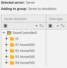
When connecting to a controller, the joint values for each robot of the controller are listed separately in the editor, for example a controller managing two or more robots.
Post Processing the Robot Program
Postprocessor
If you need to translate robot programs from your Visual Components model to the native controller, you can use the Postprocessor.
Note: The Postprocessor is available in the following products:
- Visual Components Premium
- Visual Components Premium OLP
- Visual Components Professional OLP
- Visual Components Robotics OLP
For more information on postprocessing using a Visual Components OLP product, see Translate robot program.
To translate the robot program for the real robot controller:
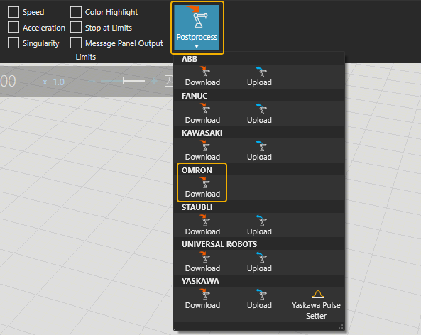
- Click the robot (or another device) which program you want to translate.
- Click Postprocess from PROGRAM ribbon tools.
- Click Download under the correct robot brand name.
- Browse the folder where you want to save the program file and give name for the file.
-
Click Save.
The file can be transferred to the robot controller
Note: In real robots, run only the robot programs that are translated from calibrated models. Otherwise, there can be unpredictable collisions and errors when executing the program.
For more information check the Visual Components Robotics OLP robot brand specific manuals on the Visual Components OLP Extranet.