Modeling

The Modeling view allows you to model new and existing components.
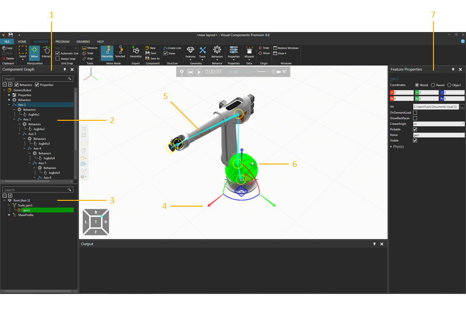
1. Component Graph Panel
2. Component Node Tree
3. Node Feature Tree
4. Manipulator
5. Visual Node Structure
6. Selected Feature
7. Properties Panel


Access

To access the Modeling view:

  • Click the MODELING tab.

Panels

The Modeling view shows, by default, the following panels:

  • Component Graph for viewing and editing the data structure of a selected component. The panel itself consists of two panes. The top pane (Component Node Tree) shows the node structure of a component as well as the component's properties and behaviors. The bottom pane (Node Feature Tree) shows the feature structure of a selected node in a component, which can include primitives, imported geometry from CAD files, physics elements, and operations that transform and manipulate other features.
  • Properties for reading and writing properties of selected objects in a component. This includes nodes, behaviors and features. Component properties are objects with their own set of properties listed in a Property task pane.

Context

The context of the Modeling view is component modeling.

You can:

  • Create, edit and link nodes to form a kinematic chain of joints.
  • Create and connect behaviors to perform and simulate internal and external tasks and actions.
  • Contain, create and manipulate CAD geometry and topology in features. This includes data analysis, clean up, regrouping and simplification of geometry in CAD files for use in small, medium and large layouts.
  • Create and reference component properties to control and limit the value of other properties within a component.
  • Use mathematical equations and expressions to define properties and make a component parametric.
  • Create static and kinematic objects as well as entities for simulating physics. This includes restitution, rigidity and elasticity.
  • Use Python 2.7 and API to implement scripts for defining component features, logic as well as the automation of tasks, actions and event handling.

Commands

By default, the following commands are shown in the Ribbon when you click the Modeling tab.

Name Description
Align Aligns a selected object using two points. Additional options are displayed in a task pane.

Settings
Align position, orientation or both and in what axis.

Snap Type
Define the type of point to select in the 3D world.

Always Snap Turns on/off the automatic snapping of a selected object along an axis or plane at intervals when using the manipulator.
Automatic Size Turns on/off the automatic calculation of intervals for snapping a selected object along an axis or plane when using the manipulator.
Behaviors Displays a list of behaviors that can be created in a selected node.
Copy Copies the current selection to the clipboard.
Create Link Creates a new child node in a selected node.
Delete Deletes the current selection.
Features Displays a list of features that can be created in a selected node.
Geometry Imports the geometry of a supported file. Additional options are displayed in a task pane, see Import Model Settings.
Hierarchy Allows a selected object and its hierarchy to be moved together when using the manipulator.
Interact Allows the pointer to jog joints and other interactive properties of objects in one or more degrees of freedom in the 3D world.
Measure Measures the distance and/or angle between two points in 3D world. Additional options are displayed in a task pane.

Mode
Measure distance, angle or both.

Settings
Define how to visualize a measurement and in which coordinate system to base measured values.

Snap Type
Define type of point to select in 3D world.

Tip: The results of a measurement are sent to Output panel.

(Manipulation) Move Allows a selected object to be moved along an axis or plane, rotated around an axis, and snapped and aligned to a point in 3D world.
(Origin) Move Allows the point of origin in active component to be moved in 3D world. Additional options are displayed in a task pane.

Apply
Save the new position and orientation of origin.

New Creates a new component in the 3D world.
Paste Adds the contents of clipboard to active area or field of workspace depending on data type.
Properties Displays a list of properties that can be created in the root node of active component.
Restore Windows Restores the workspace of current view to its default setting.
Save Saves the active component to an existing file, otherwise a new file.
Save As Saves the active component to a new file.
Select Allows for direct and indirect selection of features in the 3D world using listed commands.

Rectangular selection
Select by drawing a selection box.

Free-form selection
Select by drawing a selection path to form a closed loop.

Select all
Selects all features in the active component.

Invert selection
Forms a new selection of every feature not in current selection.

Selected Allows a selected object not its hierarchy to be moved when using the manipulator.
(Structure) Show Turns on/off the visual node structure of an active component in 3D world, including joint offsets and degrees of freedom.
(Windows) Show Displays a list of panels that can be shown/hidden from the current view of workspace.
Size Defines the interval for snapping a selected object along an axis or plane when using the manipulator.
(Origin) Snap Allows the point of origin in active component to be snapped to a location in 3D world by using one to three points. Additional options are displayed in a task pane.

Mode
Snap to one point, the midpoint of two points, or the center of an arc made by three points.

Settings
Affect position, orientation or both and in what axis.

Snap Type
Define the type of point to select in the 3D world.

Apply
Save the new position and/or orientation of origin.

(Tools) Snap Allows a selected object to be snapped to a location in 3D world by using one to three points. Additional options are displayed in a task pane.

Mode
Snap to one point, the midpoint of two points, or the center of an arc made by three points.

Settings
Affect position, orientation or both and in what axis.

Snap Type
Define the type of point to select in the 3D world.

Tools Displays a list of tools for editing nodes, features and geometry.

Split
Allows geometry in a node to be selected in 3D world, and then moved to a new Geometry feature. The selection can either be of geometry sets, faces or individual faces and must be contained in Geometry features.

Invert
Allows geometry in a node to be selected in the 3D world, and then inverted to face a different direction. The selection can either be of geometry sets, faces or individual faces and must be contained in Geometry features.

Merge
Moves selected geometry in a node into one feature. The selection must be contained in Geometry features. The first selected Geometry feature will be merged with other selected features, and those features will be deleted.

Merge faces
Merges points in selected faces.

Collapse
Collapses a selected feature and its hierarchy into a new Geometry feature.

Slice
Allows geometry in a selected feature to be sliced into a new Geometry feature by using a plane. When slicing, a point is picked in the 3D world and settings are used to define a plane at that point. Plane intersection with the geometry of a selected feature is indicated by thick red lines.

Select Identical
Allows geometry to be selected in the 3D world, and then automatically selects identical geometry.

Remove Holes
Allows geometry to be selected in the 3D world, and then automatically removes holes and gaps based on a criteria by tessellating surfaces.

Component
Extracts a selected node/feature and its hierarchy from the active component, and then forms a new component. Selected nodes will become child nodes of a new component, whereas selected features will be contained in the root node of a new component.

Link
Extracts a selected feature and its hierarchy from the active component, and then forms a new node. If features are contained in the same node, a new node will be formed at that level in the node hierarchy or as a child of the root node. If features are contained in different nodes, a new node will be formed at the upper most level in the node hierarchy or as a child of the root node.

Decimate
Reduces the data count of selected features by merging and removing vertices based on a criteria. This is a clean up operation that will try to preserve the topology of geometry, eliminate redundant vertices, and patch gaps and cracks by forming new faces.

Cylindrify
Converts selected geometry into cylinders.

Blockify
Converts selected geometry into blocks.

Assign
Sets, clears or inspects the materials of features. This can also be used to add and edit items in your materials libraries.

Add Decal
Allows geometry to be copied and used for visualizing a decal that is loaded from a source geometry file.

Mapping
Allows texture coordinates to be assigned to geometry.

Wizards Displays a list of wizards for executing automatic operations.

Action Script
Models a selected component to support the signaling of actions using I/O. The logic for I/O signal actions is defined in a Python Script labeled ActionScript and can be configured in the Actions Configuration section listed in the Properties panel for a selected component.

Convex Hull
Creates a convex around the object and replaces it with the original geometry.

Conveyor
Models a selected component as a conveyor for moving components along a path. The path can be defined by existing Frame features or auto-generated along the top face of the component bound box. Interfaces can be auto-generated to support the physical transfer of components to and from other components. Otherwise, the input and output ports of the path can be defined by existing flow type behaviors. Another option is the ability to auto-generate a Component Creator at the beginning of the path and connect its output to the input of the path.

Count Triangles
Count Triangles - Tool to count triangles. Selected Feature(s) - Count the triangles for the selected feature(s). Active Component - Count the triangles for the active component. Layout - Count the triangles for all the components in the layout.

End Effector
Models a selected component as an end-of-arm tool (EOAT) or external axis that can be physically and remotely connected to robots using signals and interfaces.

IO-Control
Models the joints of a selected component, that are assigned to a controller,to be driven to a set value by using signal events. Three Real properties will be created for each joint to define its open, closed and current value. Three Boolean signals will be created to trigger and define the value a joint should be driven to by its controller. The signal labeled [Joint_Name]ActionSignal acts as a trigger condition for a Python Script created and paired with a controller. When a joint action signal is set to 0 or 1, the script will notify its paired controller to move that joint to its open (0) or closed (1) value, for example grasp and release actions of grippers and clamps. Multiple controllers and scripts can be used to move joints independent of one another in a process. The other two signals created for a joint can indicate if the joint is in an open or closed state.

Machine Wizard
Machine Wizard can be used to turn a CAD geometry into a simulation-ready machine to be used with PLC-control, Works library, and Process Modeling. This wizard creates the necessary Properties, Behaviors, and Features automatically. To use this wizard, you need to have a component, e.g., a geometry model of a machine either created in Visual Components or imported from CAD software. The component must have at least Servo Controller behavior, and preferably the Link Structure and Joints configured to enable the add-on. When the links are configured, open the Machine Wizard. Select the node, or the location, where the machined parts will be placed. Once functionalities to add to the machine are selected, create required properties, behaviors, and features. To finalize the machine, move the frames such as product and resource location to desirable places, and the machine is ready for testing and use.