Aux (auxiliary axes) tab
NOTE: This topic is only applicable to the following Robotics OLP products:
- Visual Components Premium OLP
- Visual Components Professional OLP
- Visual Components Robotics OLP
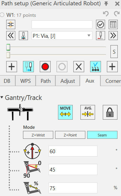
Gantry/Track
Parameters to control the calculation of Robot Positioner device
- Move: Allow the robot positioner to move during welding
- Avg (Average): The software will calculate the values for robot positioner so that it will reach all the points but is not moving during welding.
- Lock: Lock the robot positioner to current position at all the points in the weld path
- Mode: Place from which the following parameters are calculated (Z+ wrist, Z+ point, Seam)
- Azimuth: Position of robot base
- Elevation: Angle between 2nd and 5th robot joint (for gantry only)
- Stretch: distance between 2nd and 5th robot joint in % (for gantry only)
Tip: To learn to use these parameters effectively play with them and see how the robot behaves in the simulation window
Link Limits
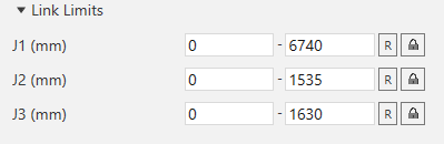
- Set the Gantry limits for needed axis.
- R = reset positioner nominal values
- Lock the needed Gantry axis
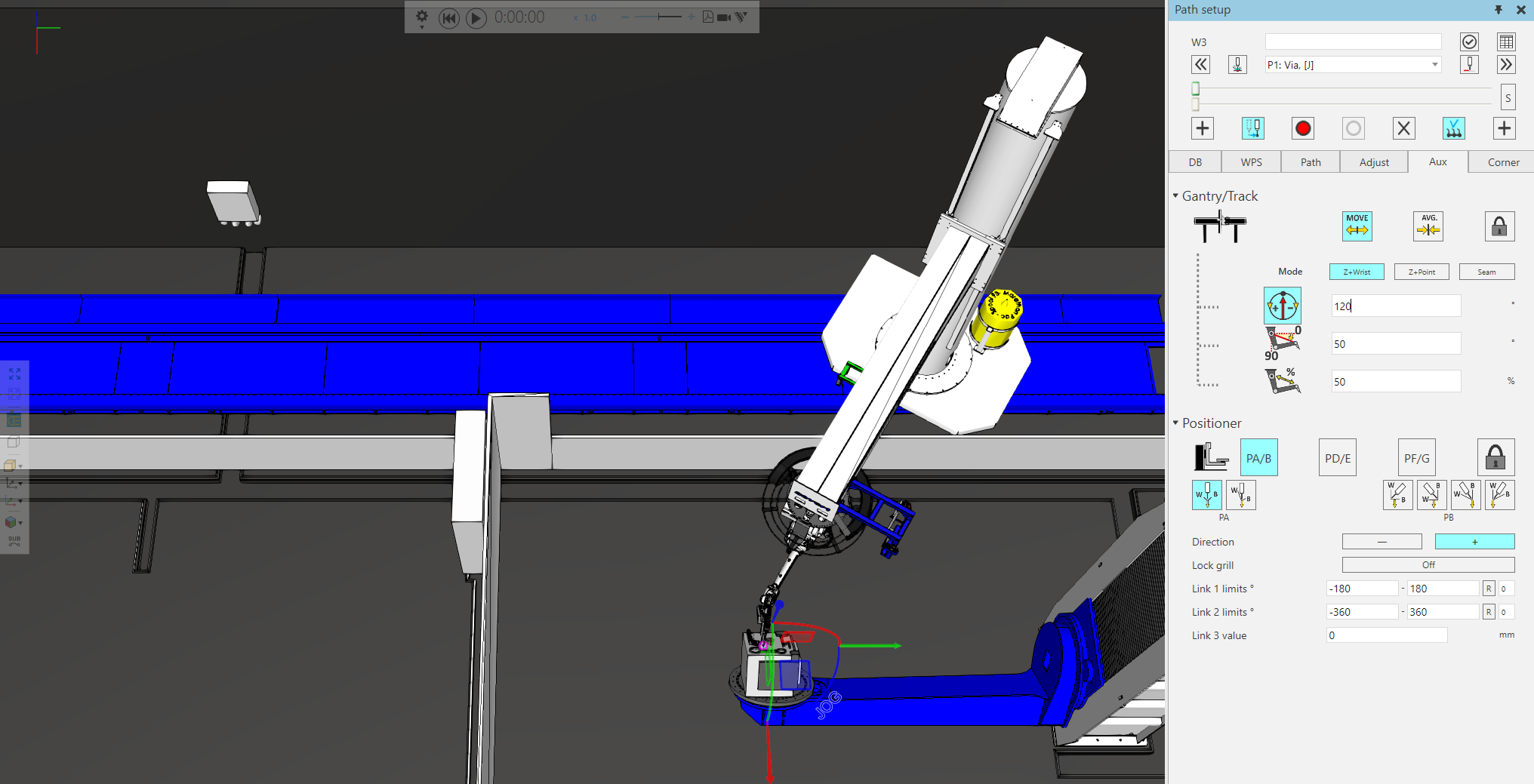
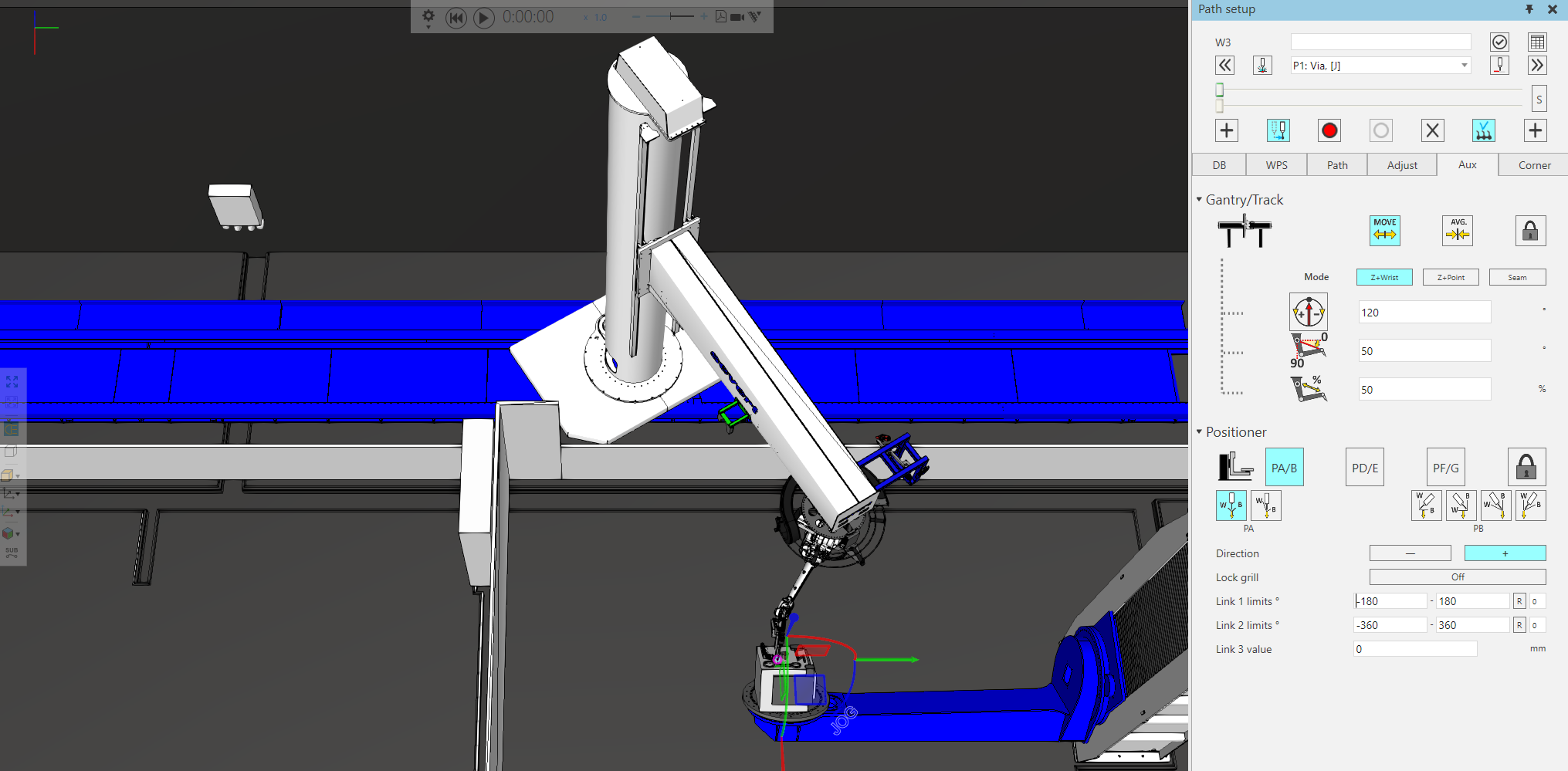
Flip rotational gantry axis
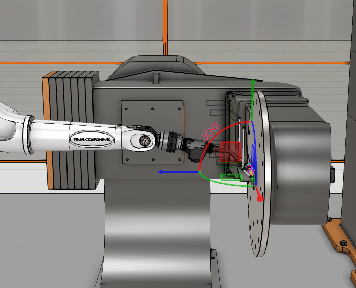
In case of a TRT/TR gantry system, while calculating the Azimuth, the gantry can achieve two possible solutions while moving the robot base, as shown in the images below.
Positioner
The user can choose from the pre-defined Welding Positions available here, and the software will automatically set the Workpiece Positioner such that the chosen position is achieved.
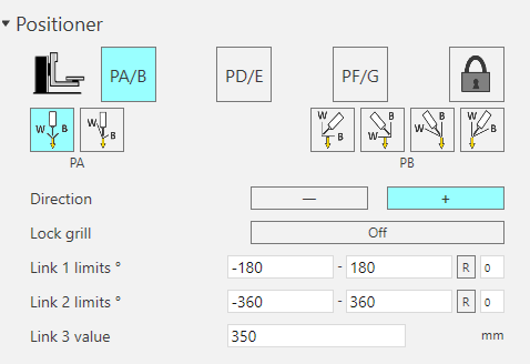
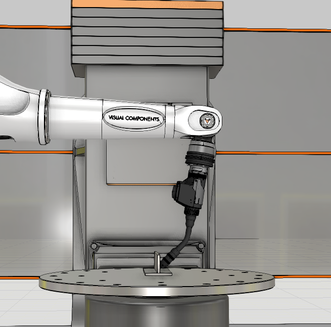
PA Position (1G/1F)
Automatically sets the Positioner to achieve Flat welding position.
There are two options. With the first option, the weld seam is maintained in the downward position. Even if you make any changes to Wire angle in the Adjust tab the Workpiece positioner will be maintained, and the robot will move.
With the second option, the wire is maintained in the downward position. Thus, any change to Wire angle from Adjust tab will move the workpiece positioner but keep the robot stationary to maintain the position.
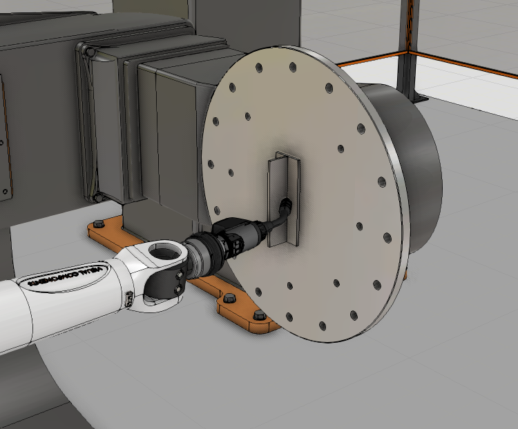
PB Position (2F)
Automatically sets the Positioner to achieve Horizontal welding position.
Also allows to set what part of the seam is upwards.
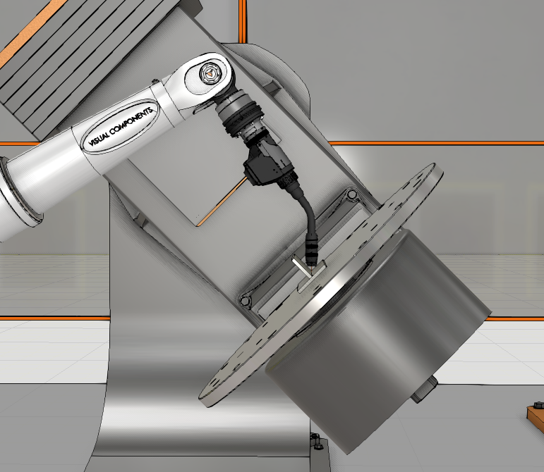
PD/PE Position (4F)

Automatically sets the Positioner to achieve Overhead welding position.
PF/PG Position
Automatically sets the Positioner to achieve Vertical welding position.
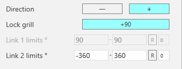
Direction: change the “configuration” of the positioner.
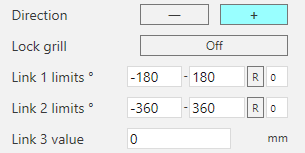
Lock Grill: lock the first axis of a 2-axis positioner to 90/-90deg value to use it as one axis positioner
Link Limits:
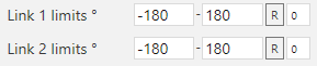
- Set the positioner limits for active weld path in degrees,
- R = reset positioner nominal values
- Set the turn value for the Positioner axes
For example for a Positioner with the axis 2 (rotating plate) having limits -720 to 720, setting:
- turn =0 → sets the axis values between -180 to 180
- turn =1 → sets the axis values between 180 to 540
- turn =-1 → sets the axis values between -540 to -180
- turn =2 → sets the axis values between 540 to 720
- turn =-2 → sets the axis values between -540 to -720
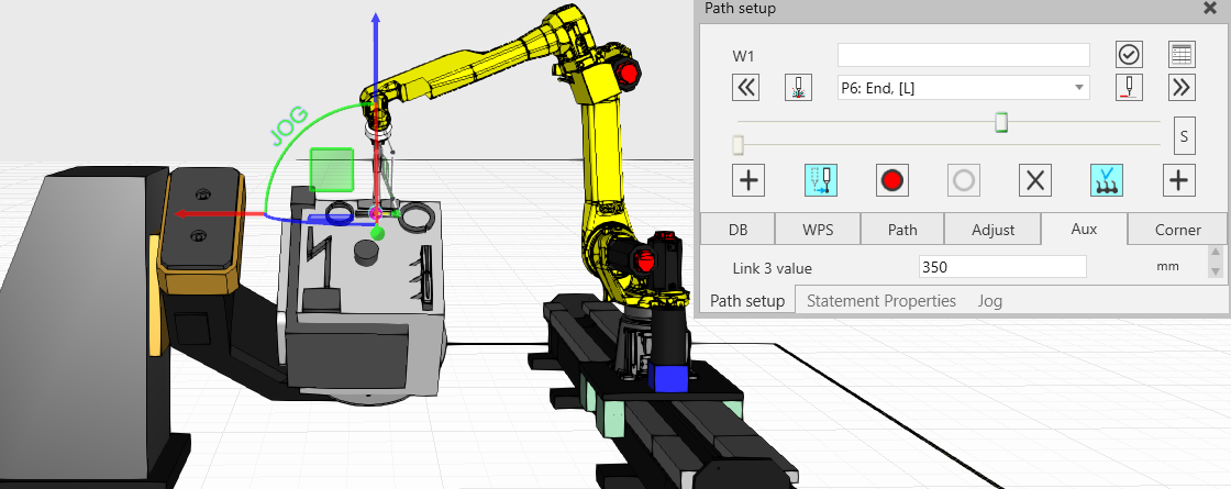
Link 3 value: For a 3 axes Workpiece Positioner, you can change the Positioner Link3 (Elevation link) values by scrolling mouse wheel in this field and see the instant update in 3D window.
Robot Joint 7 extender on Aux -tab
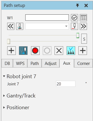
If there is a 7-axis robot arm selected, you can find “Robot joint 7” extender shown on the Aux -tab. With “Joint 7” parameter you can modify the value of 7th joint for the full path and for single points with touch-up