Linear Motion
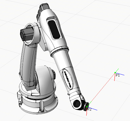
A Linear Motion statement is a motion in which a robot uses its current configuration to reach a position in the shortest distance possible.
Example. Linear motion of robot from P1 to P2
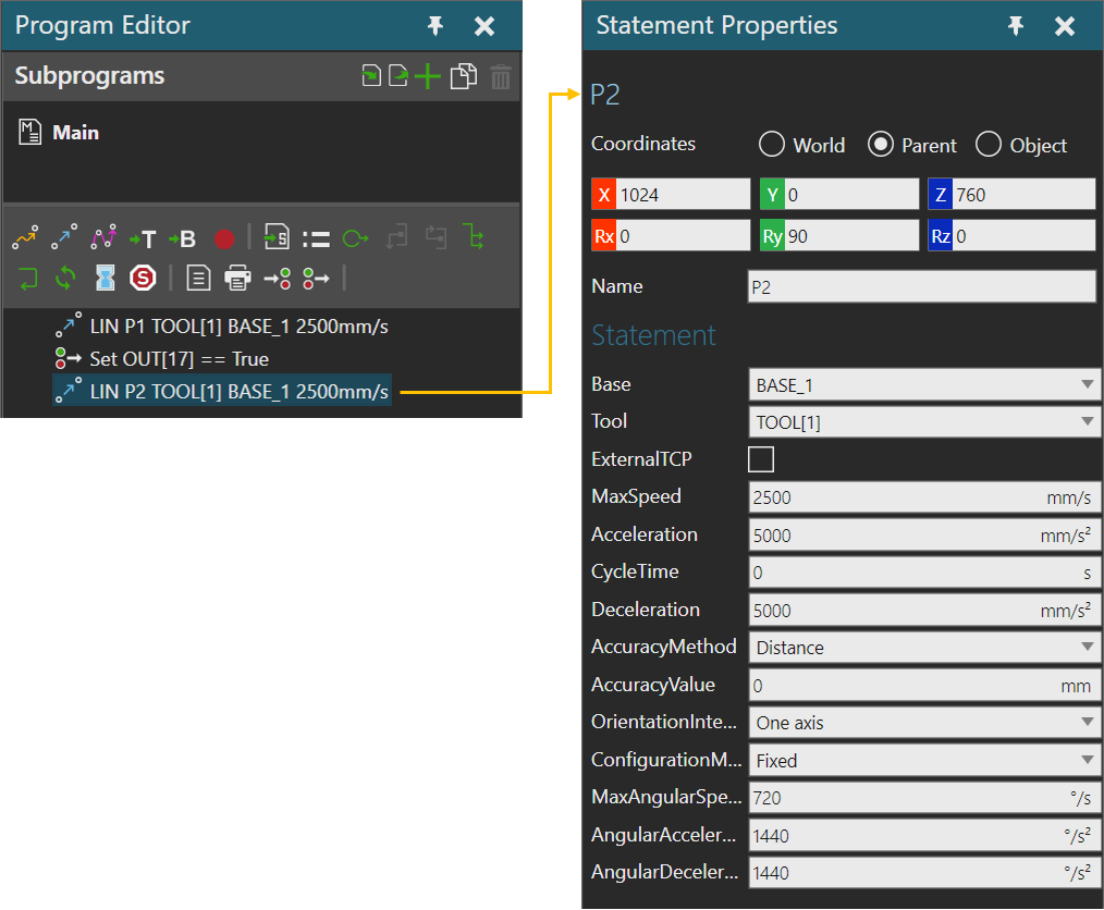
Properties
Position
| Name | Description |
| Position | Defines the position matrix using XYZ coordinates and Rx,Ry and Rz rotational values. |
| Name | Defines the name of position. |
Statement
| Name | Description |
| Base | Defines the base frame used by robot for the statement. |
| Tool | Defines the tool frame used by robot for the statement. |
| ExternalTCP | Defines the interpolation mode for position.
False uses Base to Tool interpolation. True uses Tool to Base interpolation. |
| MaxSpeed | Defines the maximum Cartesian speed (units/s) used to calculate position trajectory. |
| Acceleration | Defines the maximum Cartesian acceleration of motion (units/s^2) used to calculate position trajectory. |
| CycleTime | Defines the total elapsed time for motion, beginning to end.
A zero value means robot ignores cycle time. A value greater than zero means robot overrides speed settings to scale motion to cycle time. For example, a cycle time of 5 seconds means a motion that might otherwise take 2 seconds will now take 5 seconds. |
| Deceleration | Defines the maximum Cartesian deceleration of motion (units/s^2) used to calculate position trajectory. |
| AccuracyMethod | Defines the zone of accuracy type to use for the position. |
| AccuracyValue | Defines the limit used in AccuracyMethod. |
| OrientationInterpolationMode | Defines the orientation interpolation mode for linear movement.
One Axis uses an axis with the smallest angle of rotation to Tool. This is the default mode for Linear Motion statements. Two Axis selects either the X, Y or Z axis and its direction at Tool. The angle of rotation for the selected axis is applied first, and then other rotations are based around that axis. Three Axis interpolates either the WPR (Yaw, Pitch, and Roll) or ZYZ (Euler angles) for a target and calculates a sequence of rotations. Wrist interpolates the robot wrist joints to minimize their movement. This example shows a limitation of One Axis in which a collision occurs.
This example avoids collision by using Two Axis Z.
See Technical Notes for more information on how tool rotation is calculated and applied for linear motions. |
| ConfigurationMode | Defines the configuration mode for joints driven by robot controller
during linear motion interpolation.
Fixed uses the current configuration of robot. Follow frame uses configuration closest to previous joint values of robot, so robot will try to maintain current configuration with some small changes. Interpolate joint values uses a configuration determined by point-to-point interpolation of joint values. |
| MaxAngularSpeed | Defines the maximum angular speed (units/s) that is used to calculate position trajectory. |
| AngularAcceleration | Defines the maximum angular acceleration of motion (units/s^2) that is used to calculate position trajectory. |
| AngularDeceleration | Defines the maximum angular deceleration of motion (units/s^2) that is used to calculate position trajectory. |
- One Axis mode for orientation interpolation is the same as quaternion SLERP. It computes an axis of shortest rotation, assuming X-axis if the rotation is 180 degrees.
- Two Axis mode for orientation interpolation projects the rotation on the selected axis first, and then subtracts that rotation from the total rotation, and then computes a quaternion SLERP rotation on the remaining rotation. This produces a motion that minimizes the rotation of the selected axis which is useful for robots with axial tools such as weld guns, routers, etc. The rotations around the selected axis and the computed axis are interpolated independently.
- Three Axis mode for orientation interpolation decomposes the rotation into either its yaw-pitch-roll angler or Euler angles, and interpolates each angle independently.
- Wrist mode for orientation interpolation instructs the robot to do a joint interpolation of the robot wrist joints, and then adjusts the major axes of the robot so that the frame position follows a linear path. This mode minimizes the travel for the robot wrist joints, but the motion is different depending on the shape and size of the robot.
If the orientation interpolation mode is not Wrist mode, there is also an acceleration/deceleration profile which is calculated based on the MaxAngularSpeed, AngularAcceleration, and AngularDeceleration values. In multi-axis rotations, this is based on the rotation axis with the longest rotation. i.e. over the largest angle. In Wrist mode, the wrist joint acceleration/deceleration parameters determine the orientation interpolation acceleration/deceleration profile, thereby it does not use MaxAngularSpeed, AngularAcceleration, AngularDeceleration values. The orientation interpolation acceleration/deceleration profile is then synchronized with the position acceleration/deceleration profile as well as any external joint acceleration/deceleration profiles on the principle that all profiles are adjusted to the slowest profile so that the acceleration/drive/deceleration times are identical in order to produce the final motion.