LS Electric
About the plugin
The LS Electric plugin allows you to connect to an LS Electric controller during simulation and exchange data. For example, a program running in a virtual or physical LS Electric controller can read data from sensors and drive conveyors and actuators in a simulation.
The plugin is associated with the Connectivity feature of Visual Components Premium and can connect to one or more LS Electric controllers. The simplified workflow is the following:
- Add server
- Connect to the server
- Map variables
- Run the simulation
Requirements
The connection requires Visual Components Premium and LS Electric XG5000 software to be installed on the same PC.
Setup
- Check that your PC meets the requirements.
- Access the LS Electric controller. This can be either a simulated PLC inside the XG5000 software or a hardware controller connected to your local network.
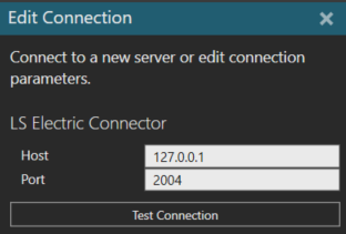
- In Visual Components, go to the Connectivity tab, select the LS Electric connectivity plugin and click Add Server. This will open the Edit Connection panel. The default Host address for a simulated PLC is 127.0.0.1 and Port is 2004. Test the connection and if the connection is ok, click Apply at the base of the panel.
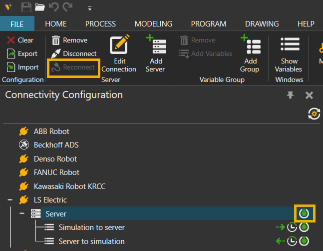
Activate the connection by selecting the LS Electric Server and either pressing Reconnect from the ribbon above or by clicking the Connect/Disconnect icon on the right side of the server. The connection is active when the icon turns green.
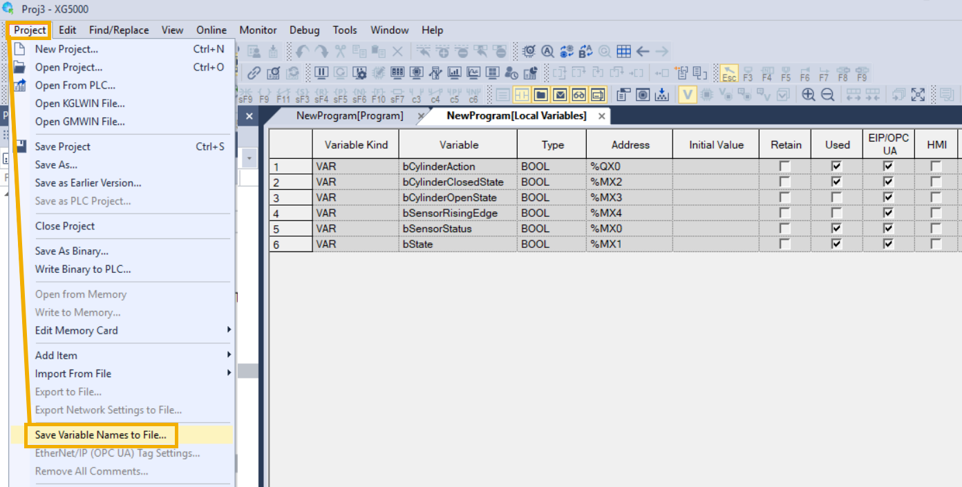
- Import the PLC symbols to Visual Components. This is done by opening XG5000 and selecting Project > Save Variable Names to File.
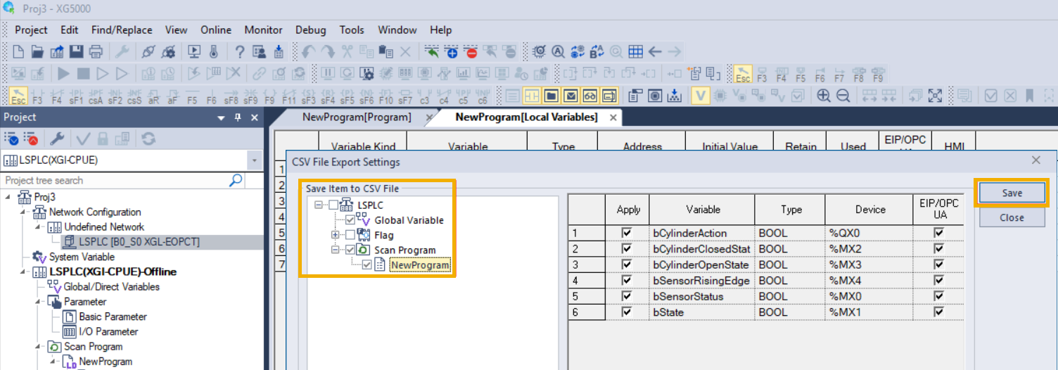
Selecting Save Variable Names to File will open a new window, where you can choose which variables will be included in the file. Make sure you have selected the necessary variables from Global Variables and from under Scan Program. Then press Save to create the variable file.
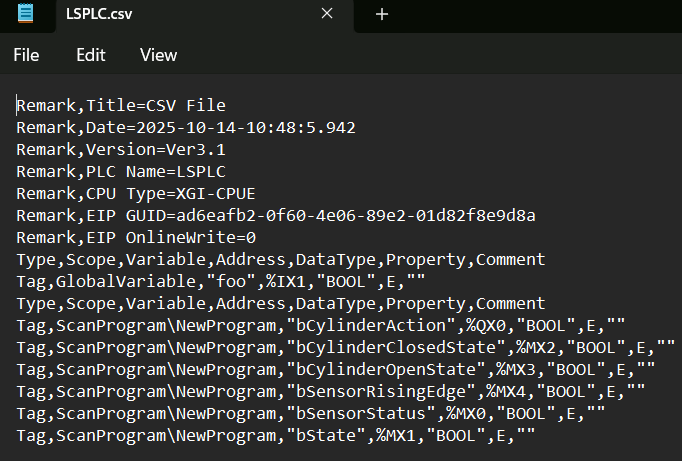
You can manually validate the file content by opening the variable file in a text editor and checking that it contains the variable definitions.
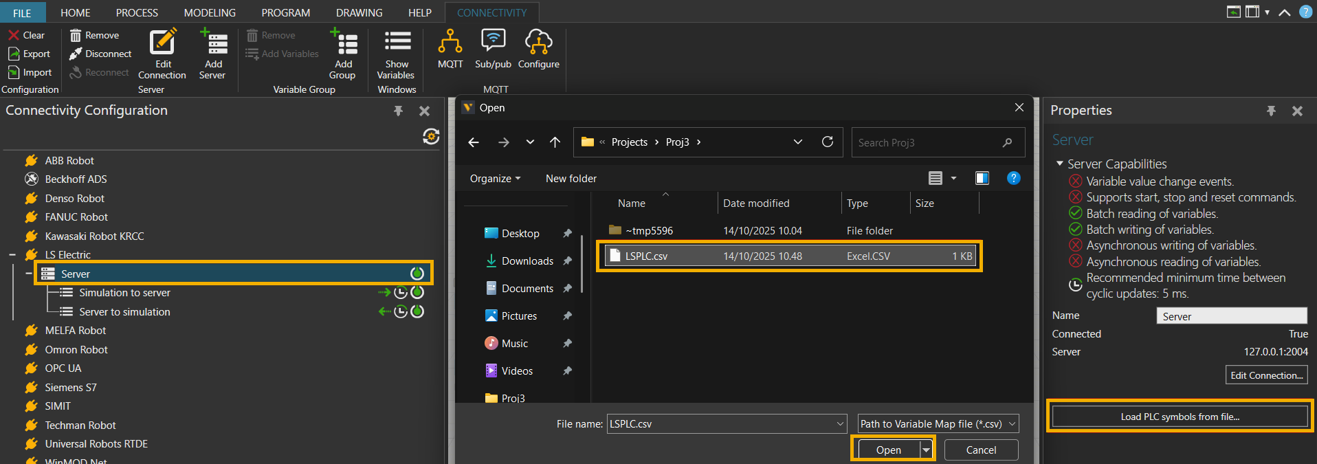
To import the variable file to Visual Components, select the LS Electric Server plugin and click on the Load PLC Symbols from file button in the Properties panel. This will open a window where you must select the previously saved variable file.
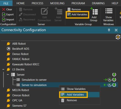
- Add variable pairs. Make sure that the server connection is active (icon turns green). Select one of the variable groups, and click Add Variables either from the ribbon above, or from the right-click menu.
The Create Variable Pairs window will open where you can select variables from the simulation and variables from the server to be paired. If some variables are missing, make sure that you have the correct variables included, and click on the Reload Structure button to reload the variables.
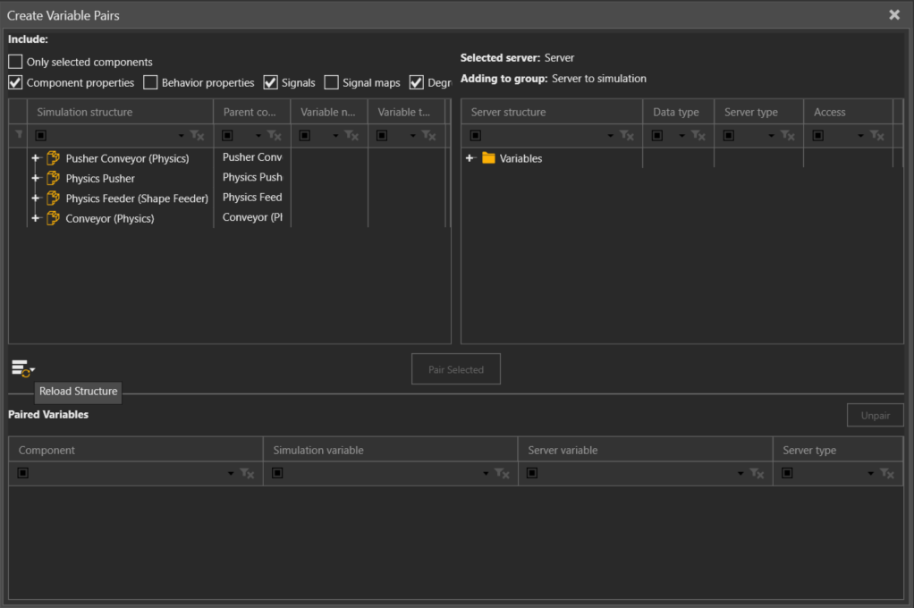
Look for variables to pair by expanding the structures. Select suitable variables on both sides and click Pair Selected to create a variable pair.
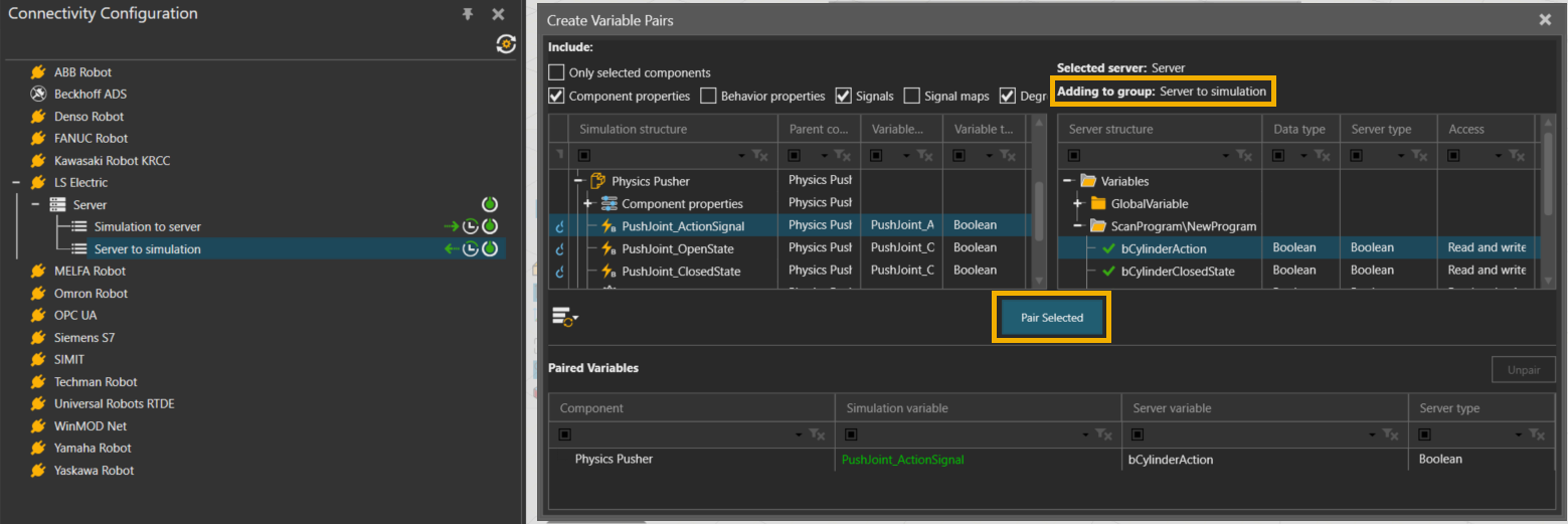
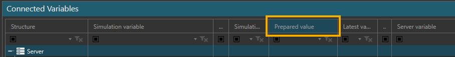
Pay attention to the variable group that you have selected to pair the correct variables for Simulation to server and Server to simulation transmit directions. - Run the simulation to start the data exchange. Observe as the simulation variables are synchronized with the PLC variables. Note that in the Connected Variables panel, the Prepared value column can be used to set values for testing.
Capabilities
You can verify the capabilities of the LS Electric plugin and subsequent server connections in the Properties panel.
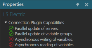
Plugin
- In the Connectivity Configuration panel, select LS Electric.
- In the Properties panel, expand Connection Plugin Capabilities.
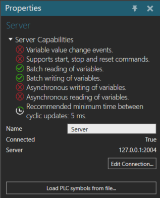
Server
- In the Connectivity Configuration panel, expand LS Electric, and then select an active server connection.
- In the Properties panel, expand Server Capabilities.
Limitations
Be aware, that there are certain limitations when using the LS Electric connectivity plugin:
- There is no browsing functionality available to discover which variables exist on the PLC. This information must be obtained separately from the PLC programming tool XG5000.
- You cannot validate if a given variable exists on the PLC. The protocol allows reading and writing various PLC memory areas, but there is no way of knowing if those memory areas are used by the PLC program as expected.
- The communication is not encrypted, and it does not support password entry. The connection should only be made within a secure network.
- Event-based update mode is not supported for Server to Simulation direction.
- The connector performs variable type conversion based on the variable’s memory size on the PLC. All integers are treated as unsigned, so negative values are not supported. All real or floating-point variables are also treated as integers, so they cannot be used directly.
Note: See the Supported Data Types topic for the variable type conversion table. - Attempting to transfer any value larger than 32 bits in memory will cause the synchronization for that variable to fail.
- Only variables in the M memory area are supported. The connector does not support variables in the I, Q, R, and W memory areas.
- Unsupported data types include WORD, DWORD, LWORD, STRING, TIME, TIME_OF_DAY, DATE, and DATE_AND_TIME.
Error handling
The following error can appear when testing a connection or attempting to connect to server:
Retrieving the COM class factory for components with CLSID ... failed due to the following error: Class not registered.
This can happen when the XGComLib64.dll is not registered on the PC. It is possible to register the DLL manually by using the command prompt.
- Navigate to the XG5000 folder in C:\XG5000.
- Open a command prompt with Administrator rights.
- Type in regsvr32 XGCommLib64.dll to manually register the LS Electric XGCommLib64.dll communication library.
If the connection to the controller is lost while the simulation is running, the data exchange will stop. So you might need to manually disconnect Visual Components from the controller and then attempt to reconnect to verify the connection is lost.
Sometimes the connection state can be left in an undefined state. In these situations, it is best to save the simulation layout and restart Visual Components. In uncertain situations it can also help to remove and recreate the server connection.