Allen-Bradley PLC
Note: In addition to the setup information below, refer to the video lesson (in English) on the Visual Components Academy.
About the plugin
The Allen-Bradley plugin allows you to connect a running Allen-Bradley PLC with a loaded program. The plugin supports Micro800, CompactLogix and ControlLogix 5000 controller families. The controller itself can be real or virtual, for example an emulated controller running in FactoryTalk Echo. You can have multiple connections to one or more controllers.
Important:
- For security reasons, a connection to legacy controllers like MicroLogix and SLC 5000 is disabled.
- A connection to GuardLogix controllers is possible as is data exchange with Flex 5000 modules and a Logix SIS controller.
- However, Visual Components itself is not safety-rated nor has a safety integrity level (SIL).
- As a result, data exchange during a simulation should be done in safe conditions albeit virtually.
Terminology
- Allen-Bradley – The brand name of the PLC types owned by Rockwell.
- Rockwell Automation (Rockwell) – The owner of the Allen-Bradley line of factory automation equipment including its PLCs and software.
- FactoryTalk Echo – Software used to emulate CompactLogix and ControlLogix controllers.
- Studio 5000 – Software, specifically Logix Designer used to configure, program, build and manage projects for Allen-Bradley Logix type controllers.
- Connected Components Workbench (CCW) – Like Studio 5000, but for Micro800 controllers and includes a simulator.
Setup
Note: In addition to the setup information below, refer to the video lesson (in English) on the Visual Components Academy.
Make sure you have installed the necessary Rockwell tools on your device and properly configure the PLC before creating this workflow. If you plan to use a simulated Micro800 controller, you should use CCW. If you plan to use an emulated Logix controller, it is recommended that you use FactoryTalk Echo.
Step 1. Add Server
You can manually add a new PLC connection, import a configuration file, or load a layout with a configured PLC connection.
New Configuration
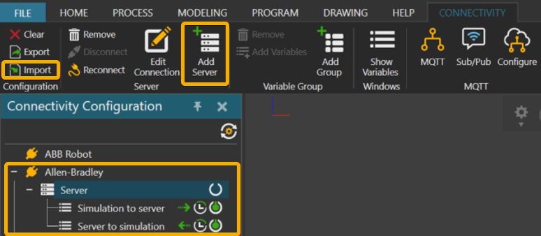
Click the Connectivity tab, and then in the Connectivity Configuration panel, do one of the following:
- Click the Allen-Bradley plugin, and then on the Connectivity tab, in the Server group, click Add server.
- Right-click the Allen-Bradley plugin, and then click Add Server.
Note: This configuration is saved with your layout and can also be exported as an XML file.
Import Configuration
A configuration file is in XML format and well-suited for cases where you need to automatically pair a lot of variables or need to share the connection settings with another user.
- In the Connectivity tab, in the Configuration group, click Import.
- Import the XML file for your PLC connection.
Load Configuration
- Load a layout in the 3D world that has already been configured for a PLC connection.
- Click the Connectivity tab, and then in the Connectivity Configuration panel, verify the connection is listed under the Allen-Bradley plugin.
Step 2. Verify Network Connection
In most cases, you need to edit the connection and test it with your PLC. This includes the network address to the PLC, its type and optionally a list of variables on the device which would otherwise not be known when connecting to it. Generally, all global and local variables are discovered when connected to the PLC.
Important: The plugin does not support username and password authentication, for example enhanced security cases using role-based access control (RBAC). The PLC must allow for anonymous read/write of the tags you want to use with the simulation.
Editing Connection
- Click the Connectivity tab, and then in the Connectivity Configuration panel, under the Allen-Bradley plugin, select your PLC connection.
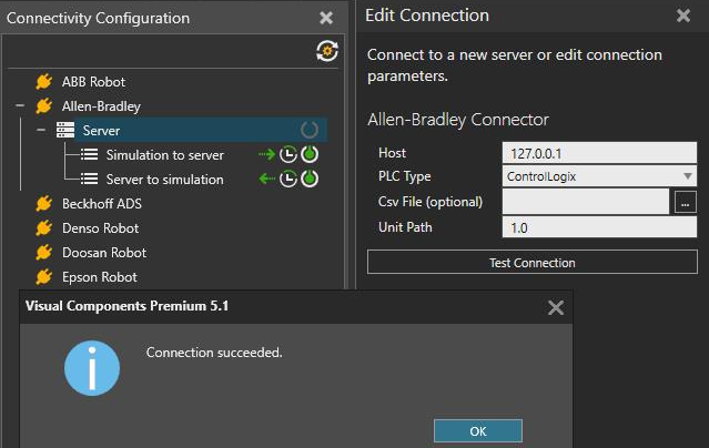
- In Edit Connection, set the IP address or hostname for the PLC and its type. When connecting to a ControlLogix controller, you also need to specify a routing path to the device in its chassis. The default path is 1.0 corresponding to slot 0 in the chassis, and 1.1 would correspond to slot 1.
- Click Test Connection.
- If you get Connection succeeded message, click OK and then click Apply to accept the changes.
Troubleshooting
- Do one of the following:
- If you are using a Micro800 controller, verify that you can connect to the device using CCW and/or the machine running Visual Components.
- If you are using a Logix controller, verify you can connect to the device using Studio 5000 and/or the machine running Visual Components.
- If the device is not reachable, verify the device has an active network. Do one of the following:
- If you are using CCW, verify or configure a new driver for the device via RSWho (RSLinx Classic Lite). If you are using CCW with simulator, you must configure the network driver for it, otherwise the simulator is not accessible via Ethernet.
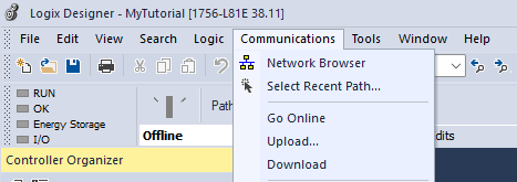
- If you are using Studio 5000, verify or configure a new driver for the device via Who Active (FactoryTalk Linx) or you can check the Network Browser from the Communications dropdown menu. If you are using FactoryTalk Echo, the emulated controller should be listed as an emulated Ethernet network.
- If a connection is still not possible, refer to Rockwell support for issues with your PLC and its communication capabilities.
Step 3. Activate Connection
If you have successfully added and verified a connection to a PLC, you are now ready to activate the connection.
Activate Connection
- Click the Connectivity tab, and then in the Connectivity Configuration panel, under Allen-Bradley, click your PLC connection.
- To activate the connection, click on the Connect/Disconnect button, and then in the Properties panel, under Server Capabilities, verify Connected is set to True.
Deactivate Connection
To deactivate the connection, click on the Connect/Disconnect button, and then in the Properties panel, under Server Capabilities, verify Connected is set to False.
Step 4. Pair Variables
The pairing of simulation variables with PLC tags is the same workflow as other connectivity plugins. In most cases, you are not required to export a list of variables or tags from the PLC and then import that list into Visual Components. The plugin can discover and fetch global variable lists and local tags used in programs on the PLC.
PLC Variable Editor
In rare cases, you might need to import a list of variables and/or use an advanced editor accessible via Server Properties for specifying one or more tags and their memory location on the PLC.
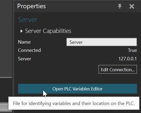
The advanced PLC Variable Editor gives you more control on the tags that exist in the PLC.
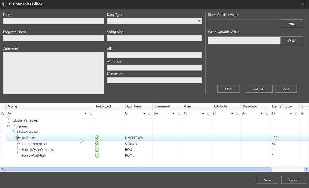
With the PLC Variable Editor, you can:
- View all tags that were fetched from the connected PLC. The bottom view of the editor shows all initialized tags on the PLC, those that were fetched and their initialization state.
- Change parameters for tags.
- Add new tags. This works only if the tag is present in the PLC and is initialized before adding.
- Read/Write data from/into the tag. For example, you can manually read/write the tag.
- Remove unused tags. As a result, these tags would not be available for pairing with simulation variables.
Supported data types
The Allen-Bradley plugin supports read/write of the following data types. Be aware the plugin can read/write members of a user-defined data type (UDT). The plugin can also read/write the external variables of add-on instructions or function blocks (FB). Access to internal variables of add-ons is disabled in the plugin.
| Allen-Bradley Type | .NET Type |
| BOOL | System.Boolean |
| BYTE | System.Byte |
| SINT | System.SByte |
| USINT | System.Byte |
| INT | System.Int16 |
| UINT | System.UInt16 |
| DINT | System.Int32 |
| UDINT | System.UInt32 |
| LINT | System.Int64 |
| REAL | System.Single |
| STRING | System.String |
| TIME | System. TimeSpan |
| User-defined data type (UDT) | Struct |
| Add-on Instruction (Function Block) | Struct |