Epson Robot
Note: In addition to the setup information below, refer to the video lesson (in English) on the Visual Components Academy.
About the plugin
The Epson Robot plugin allows you to connect to an Epson robot controller during simulation and exchange data. For example, a program running in a virtual or physical Epson controller can drive the joints of an Epson robot in a simulation, read data from sensors, and set outputs for picking and placing products.
The plugin is associated with the Connectivity feature of Visual Components Premium and can connect to one or more Epson robot controllers using RC+ 8.0. The simplified workflow is the following:
- Add server
- Connect to the server
- Map variables
- Run the simulation
Terminology
- RC+ – Industrial automation development software provided by Epson which includes an API and offline programming tools for Epson robot projects. The Epson Robot plugin supports RC+ 8.0 which can for example connect to RC700 and RC800 controllers.
Note: Older RC+ 7.0 projects can be supported but need to be rebuilt using RC 8.0. - RC+ Express – A simplified version of RC+ software used for creating Epson robot programs.
- SPRJ – The file format and project file for Epson robots.
- VRC – Virtual controller for Epson Robot. Virtual controllers are installed and run locally using RC+ and require a Basic or higher RC+ license which you can purchase from Epson.
Note: Be aware that RC+ limits you to running only one VRC instance at a time, not multiple instances. For example running one will cancel any others that might have been in use on the PC. - RC+ API – The technology used to communicate and work with Epson Robot projects.
- SPEL+ – Programming language for Epson robots.
- SPEL – In RC+ API context, a server object used for connecting and communicating with virtual and real Epson controllers.
- On a PC, the RC+ API limits you to one active SPEL object.
- As a result, you can have a one-to-one connection for a VRC or a one-to-many connection when working with real controllers.
- Refer to RC+ manuals for more details.
- I/O – (Input/Output).
Read and Write Support
Read and Write table
| Type | Read | Write | Notes |
| Robot controller digital inputs and outputs |
Yes |
Yes | Signals |
| Current joint values from any robot of the connected controller |
Yes |
No | Per safety reasons |
Requirements
The connection requires Visual Components Premium and a licensed version of RC+ 8.0 with the API package installed on the same PC. If you plan to connect a real Epson controller, ensure the controller is configured to use the RC+ API option.
Note: Refer to your local Epson provider for licensing and other specifics since Visual Components is not an Epson distributor.
Setup
Note: In addition to the setup information below, refer to the video lesson (in English) on the Visual Components Academy.
- Check that your host PC meets the requirements.
- Access the Epson robot controller.
- In Visual Components, add a new server with the plugin.
- Do one of the following to configure the connection:
- For VRC, select Virtual as the connection type. Be aware that Visual Components will load a VRC using RC+ and manage its state. Use RC+ if you need to create or edit a virtual or Ethernet connection.
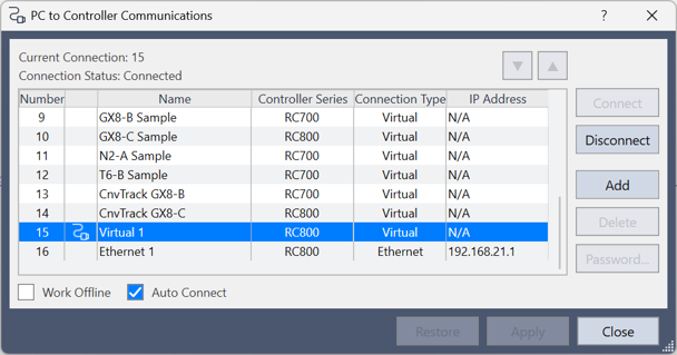
To load the VRC with a project, specify a path to a SPRJ file in Project Path. A project might specify a connection and autofill the Virtual Controller field. However, you can load a VRC without a project or choose any virtual controller from the list to use for the connection. If you do not see the target controller in the Virtual Controller list, click Scan Controllers. This will read the “PC to Controller Communications” data in your RC+ setup and update the list.
You can click Test Connection to verify that Visual Components can load the VRC with or without a specified project. This process can possibly take longer than 60 seconds since Visual Components, similar to RC+ software, will initialize and load the VRC. - For a real controller, select Real and then the corresponding connection type in Controller. Like Virtual, the Controller list is derived from the “PC to Controller Communications” data in your RC+ setup. Be aware that an Ethernet connection with a controller may require a password.
- For VRC, select Virtual as the connection type. Be aware that Visual Components will load a VRC using RC+ and manage its state. Use RC+ if you need to create or edit a virtual or Ethernet connection.
- Connect to the controller. Upon successful connection, you will receive feedback in the Output panel about the controller, its robots and I/O. Remember that a virtual connection will load a VRC and possibly take longer than 60 seconds to complete on your PC.
- Map the variables.
- Run the simulation.
To help with RC+ projects, the Server Properties panel for the connection provides additional tools and options which are detailed as follows.- Options to Start, Stop and Reset with simulation.
- By default, these options are enabled to sync the runtime state of a Visual Components simulation with the execution of tasks on the connected controller.
- For example, starting the simulation will start the main/default task on the controller.
- Use Task Index to specify a different task.
- Use Open Task Manager View to manage the state of tasks.
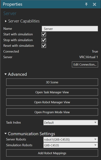
- Server indicates the connection type (VRC or Real) and name.
- 3D Scene opens an RC+ window for visualizing the 3D scene of the controller. That is, the scene derived from the project on the controller.
- Open Robot Manager View opens an RC+ window for performing actions specific to the robot of the controller, such as managing the motor state, jogging, and editing positions.
- Using this view with the 3D Scene window is helpful to verify that the robot model in Visual Components is moving correctly via the connection.
- From this window you can also access RC+ I/O monitor and Command windows with limitation.
- As a result, it is recommended to use the Open Program Mode View in most workflow cases.
- Open Program Mode View opens a RC+ software window that is tied to Visual Components. As a result, you do not need to run a separate session of RC+ software when working with the controller and project in Visual Components. This streamlined approach gives you access to all RC+ windows and functionality includes the Run window that is used for starting tasks on the controller.
- Add Robot Mappings allows you to map an Epson robot in your Visual Components layout with a connected controller. This map will auto-generate variable pairs for the robot joint values to be derived from the controller during the simulation. You can edit the added variable pairs as well as make your own via the corresponding variable group.
- Options to Start, Stop and Reset with simulation.
Capabilities
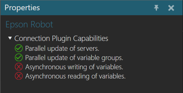
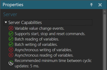
You can verify the capabilities of the Epson Robot plugin and subsequent server connections in the Properties panel.
Plugin
- In the Connectivity Configuration panel, select Epson Robot.
- In the Properties panel, expand Connection Plugin Capabilities.
Server
- In the Connectivity Configuration panel, expand Epson Robot, and then select an active server connection.
- In the Properties panel, expand Server Capabilities.
Connection Settings
An Epson Robot plugin connection requires an Epson robot controller to have either a virtual or real connection type defined in the PC to Controller Communication settings for RC+.
Each connection in Visual Components is a client to the controller and is not meant to remotely operate the robot.
Error handling
- If the connection to the controller is lost, the exchange of data will stop.
- The plugin expects an event to be received from the controller in such cases.
- If the event is not received, you might need to manually disconnect Visual Components from the controller and then attempt to reconnect to verify that the connection is lost.
- If you receive an error related to a task on the controller, resolve this using the Open Task Manager View or Open Program Mode View windows. Otherwise, reset the Visual Components simulation and troubleshoot the error in RC+.
- If you cannot load a VRC, attempt to load multiple VRCs or attempt a many to one connection to a single VRC, you will likely encounter an error.
- Generally, failure to load a VRC is caused by licensing in RC+ or corruption of the VRC and project. If a VRC is corrupted, the workaround recommended by Epson is to reinstall RC+ on the PC.
- Since RC+ limits you to running one VRC instance, attempting to run a second results in the first VRC instance being stopped while the other is being loaded. It is recommended to keep one connection active and disable all other connections when you want to test projects with different VRCs.
- If you cannot connect to a real controller, check the connection definition in RC+ and if a password is required for the connection. Also check that the controller is reachable via network and that the RC+ API option is active in the controller.
- Be aware that Visual Components does not have access to a real Epson controller. As a result, issues related to connecting to one controller and/or multiple controllers must be handled by Epson. Issues with the Epson Robot plugin, however, should be reported to Visual Components Support.
Limitations
- Joint values cannot be written to the robot controller per safety reasons.
- RC+ limits you to running only one VRC instance at a time.
Compatibility
The Epson Robot plugin was developed using RC+ 8.0 and supports a connection to any Epson robot that is compatible with that technology.
Supported data types
The Epson Robot plugin supports access to standard and extended input and output signals and mechanical units joint data.
| Epson Robot Type | .NET Type | or | VC PROPERTY TYPE |
| DigitalInput | System.Boolean | VC_BOOLEAN | |
| DigitalOutput | System.Boolean | VC_BOOLEAN | |
| Joint | System.Double | VC_REAL |