Nachi Robot
Note: In addition to the setup information below, refer to the video lesson (in English) on the Visual Components Academy.
About the plugin
The Nachi Robot plugin allows you to connect to a Nachi robot controller during simulation and exchange data. For example, a program running in a virtual or physical Nachi controller can drive the joints of a Nachi robot in a simulation and set outputs for picking and placing products.
The plugin is associated with the Connectivity feature of Visual Components Premium and can connect to one or more Nachi robot controllers. The simplified workflow is the following:
- Add server
- Connect to the server
- Map variables
- Run the simulation
Terminology
- FD on Desk – Offline programming software and VRC for Nachi robots
- FD – Type of Nachi controller
- CFD – Type of Nachi controller
- I/O – (Input/Output).
Read and Write Support
Read and Write table
| Type | Read | Write | Notes |
| Robot controller standard and fixed I/O signals |
Yes |
Yes | Fixed I/O are read-only |
| Current joint values from any mechanism of the connected controller |
Yes |
No | |
| Robot controller variables | Yes | Yes | Integer, Real and String variables |
Setup
Note: In addition to the setup information below, refer to the video lesson (in English) on the Visual Components Academy.
- Access the Nachi robot controller.
- The plugin connects to the robot controller, so the virtual or physical robot controller should be accessible via a direct network connection (IP address). For virtual controllers, make sure they are loaded in FD on Desk.
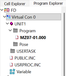
- The plugin connects to the robot controller, so the virtual or physical robot controller should be accessible via a direct network connection (IP address). For virtual controllers, make sure they are loaded in FD on Desk.
- In Visual Components, add a new server with the plugin and connect to the controller.
- The default port number for a connection with the Nachi controller is 9876. In projects involving multiple controllers, each controller has its own unique port number for communication. This is typically an increment of 9876, so the second controller would by default use port 9877.
- Map the variables.
- For example, map the VALUE property of each degree of freedom (DOF)/Joint of the robot component to a joint of the corresponding mechanical unit in the controller. This way, the controller drives the robot in the 3D world. If the controller manages multiple mechanisms (robot arms, tracks, positioners, end effectors) each mechanism and its axes are grouped together and indexed according to Nachi controller configuration.
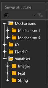
- For simulating actions such as grasp/release, map the outputs of the robot component for those actions to the I/O of the controller you will use for those actions.
- For example, map the VALUE property of each degree of freedom (DOF)/Joint of the robot component to a joint of the corresponding mechanical unit in the controller. This way, the controller drives the robot in the 3D world. If the controller manages multiple mechanisms (robot arms, tracks, positioners, end effectors) each mechanism and its axes are grouped together and indexed according to Nachi controller configuration.
- Run the simulation.
- Simulate to start the exchange of data. Note that in the Connected Variables panel, the Prepared value column can be used to set values for testing.

- Simulate to start the exchange of data. Note that in the Connected Variables panel, the Prepared value column can be used to set values for testing.
Capabilities
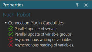
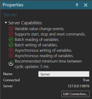
You can verify the capabilities of the Nachi Robot plugin and subsequent server connections in the Properties panel.
Plugin
- In the Connectivity Configuration panel, select Nachi Robot.
- In the Properties panel, expand Connection Plugin Capabilities.
Server
- In the Connectivity Configuration panel, expand Nachi Robot, and then select an active server connection.
- In the Properties panel, expand Server Capabilities.
Error handling
- If connection to controller fails, verify the IP address and port number of the controller is correct and then try again. If the issue persists, verify you can access the controller over your network and check your firewall settings.
- If the connection is denied, verify the controller is in a state to support client connection. For example, a virtual robot controller in FD on Desk needs to be loaded in the project to connect to it. In some cases, you might need to manually toggle the motor from on/off state.
- If writing an I/O fails, check if the I/O is mapped to a fixed signal on the controller which can affect write access.
Limitations
- Event-based update mode is not supported therefore updates are done cyclically.
- Joint values cannot be written to the robot controller for safety reasons.
Compatibility
The Nachi Robot plugin was developed using FD on Desk III software and has been tested with virtual and real FD and CFD controllers.
Supported data types
The Nachi Robot plugin supports access to digital signals, mechanical units joint data and global variables used for programming.
| Nachi Robot Type | .NET Type |
| I/O | System.Boolean |
| Joint | System.Double |
| String variable | System.String |
| Integer variable | System.Double |
| Real variable | System.Double |
Post Processing the Robot Program
The OTC DAIHEN | NACHI postprocessor can be used to translate programs of 6 and 7 axis robots.
Postprocessor
If you need to translate robot programs from your Visual Components model to the native controller, you can use the Postprocessor.
Note: The Postprocessor is available in the following products:
- Visual Components Premium
- Visual Components Premium OLP
- Visual Components Professional OLP
- Visual Components Robotics OLP
For more information on postprocessing using a Visual Components OLP product, see Translate robot program.
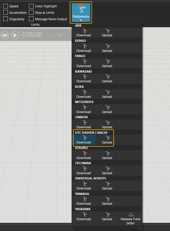
To translate the robot program for the real robot controller:
- Click the robot (or another device) which program you want to translate.
- Click Postprocess from PROGRAM ribbon tools.
- Click Download under the correct robot brand name.
- Browse the folder where you want to save the program file and give name for the file.
- Click Save.
- The file can be transferred to the robot controller.
Note: In real robots, run only the robot programs that are translated from calibrated models. Otherwise, there can be unpredictable collisions and errors when executing the program.
For more information check the Visual Components Robotics OLP robot brand specific manuals on the Visual Components OLP Extranet.