SIMIT IPC
About the plugin
The SIMIT IPC plugin allows you to connect Visual Components to a Siemens SIMIT simulation running on the same PC and exchange signal values during simulation. For example, a SIMIT model can drive conveyors and sensors in a Visual Components layout, and Visual Components can send sensor states back to SIMIT.
The plugin works together with the Visual Components IPC coupling, an external coupling that you add to your SIMIT project. Optionally, the plugin can also control the SIMIT simulation (open, initialize, run, stop, reset and close it) and make SIMIT follow the simulation speed of Visual Components.
The plugin is associated with the Connectivity feature of Visual Components Premium and can connect to one or more Visual Components IPC couplings. The simplified workflow is the following:
- Add the Visual Components IPC coupling to your SIMIT project and define its signals
- Add server
- Connect to the server
- Initialize the SIMIT simulation
- Map the variables
- Run the simulation
Note: SIMIT IPC replaces the SIMIT plugin. The SIMIT plugin uses SIMIT communication that is deprecated as of SIMIT V11.3.
Terminology
- Coupling – in SIMIT, the part of a project that connects the simulation to external hardware or software. The Visual Components IPC coupling connects SIMIT to Visual Components.
- IPC (inter-process communication) – communication between applications running on the same PC.
- RCI (Remote Control Interface) – SIMIT interface that lets another application control the SIMIT simulation.
- Armed – the coupling is prepared and waiting for SIMIT to start the simulation.
- Time slice – the cycle time SIMIT uses to calculate and exchange the coupling signals.
- Input/Output – SIMIT names coupling signals from the point of view of the coupling partner, in this case Visual Components:
- An input (From SIMIT) is written by SIMIT and read by Visual Components.
- An output (To SIMIT) is written by Visual Components and read by SIMIT.
Read and Write Support
Read and Write table
| Type | Read | Write | Notes |
| Coupling inputs (From SIMIT) | Yes | Yes | Binary, Integer and Analog signals |
| Coupling outputs (To SIMIT) | No | Yes | Binary, Integer and Analog signals |
| SIMIT signals that are not coupling signals | No | No | Connect them to coupling signals in SIMIT charts |
| SIMIT simulation state | Yes | Yes | Requires RCI. Open, Init, Run, Stop, Reset and Close |
Requirements
- The connection requires Visual Components Premium and Siemens SIMIT SP V10.3 or later (recommended V11.3) to be installed on the same PC.
- The Visual Components IPC coupling must be installed in SIMIT. To begin, visit the Visual Components Downloads page to download the installer.
- The demo version of SIMIT does not support external couplings.
- Optional: simulation control uses the SIMIT Remote Control Interface (RCI) on port 50800. The SIMIT license must allow external clients.
Setup
- Install the coupling:
- Close SIMIT.
- Run the Visual Components IPC coupling download Visual-Components-SiemensIpc-Coupling-Installer.exe. And if necessary, accept any Administrator prompts.
- If a firewall message appears, click OK.
- Following the installation, check that the folder C:\Program Files (x86)\Siemens\Automation\SIMIT\SIMIT SF\couplings\Visual Components IPC exists.
- Add the coupling to your SIMIT project:
- Open your project in SIMIT SP.
- In the project navigation, expand the Couplings folder.
- Add a new coupling and select Visual Components IPC under External Couplings.
- In the coupling properties, leave Simulation Project and Simulation Project Part empty, unless the project has several Visual Components IPC couplings.
Note: Optionally check that Isochronous is selected and set the Time slice. - On the coupling toolbar, click Edit signals and define the signals:
- Signal name, Data type (Binary, Integer or Analog) and Direction (From SIMIT for signals that Visual Components reads, To SIMIT for signals that Visual Components writes).
- Optionally, Initial value and Description.
- Name
- Direction
- Type
- Close the editor and click Yes to apply the changes.
- Connect the coupling signals in your SIMIT charts.
- Save the project, but do not start the simulation yet in SIMIT SP.
Note: A coupling must have at least one signal, otherwise SIMIT cannot initialize the simulation.
Use Export signals to save the current list. Initial values and descriptions will not be included in the file.
- Connect Visual Components to SIMIT:
- Check that your host PC meets the requirements, and that SIMIT SP is running with your project open and that the simulation in SIMIT SP has not started.
- In Visual Components, go to the Connectivity tab, and in the Connectivity Configuration panel select the SIMIT IPC connectivity plugin.
- Optionally, in the Properties panel, set the Operating Mode and Simulation Control. See Connection settings.
- Press Add Server:
- If your SIMIT SP project has one Visual Components IPC coupling instance, in the Edit Connection dialog, leave the Simulation project and Simulation project part empty, and click Apply.
- If your SIMIT SP project has more than one Visual Components IPC coupling instances, in the Edit Connection dialog, complete the Simulation project and Simulation project part fields. And in SIMIT SP in the Visual Components IPC coupling do the same.
- Connect to the server. Visual Components arms the coupling, and it waits for SIMIT SP to start the simulation. The plugin also connects to SIMIT simulation control (RCI) automatically.
- Initialize the SIMIT simulation:
- With Simulation Control set to Manual: in the plugin Properties panel, under Manual Simulation Control (RCI), click Open and then Init. Alternatively, start the simulation in SIMIT.
- With Simulation Control set to Auto: the SIMIT simulation is opened and initialized automatically when you connect.
- When SIMIT has initialized the simulation, the coupling signals appear under Inputs and Outputs. Then map the variables.
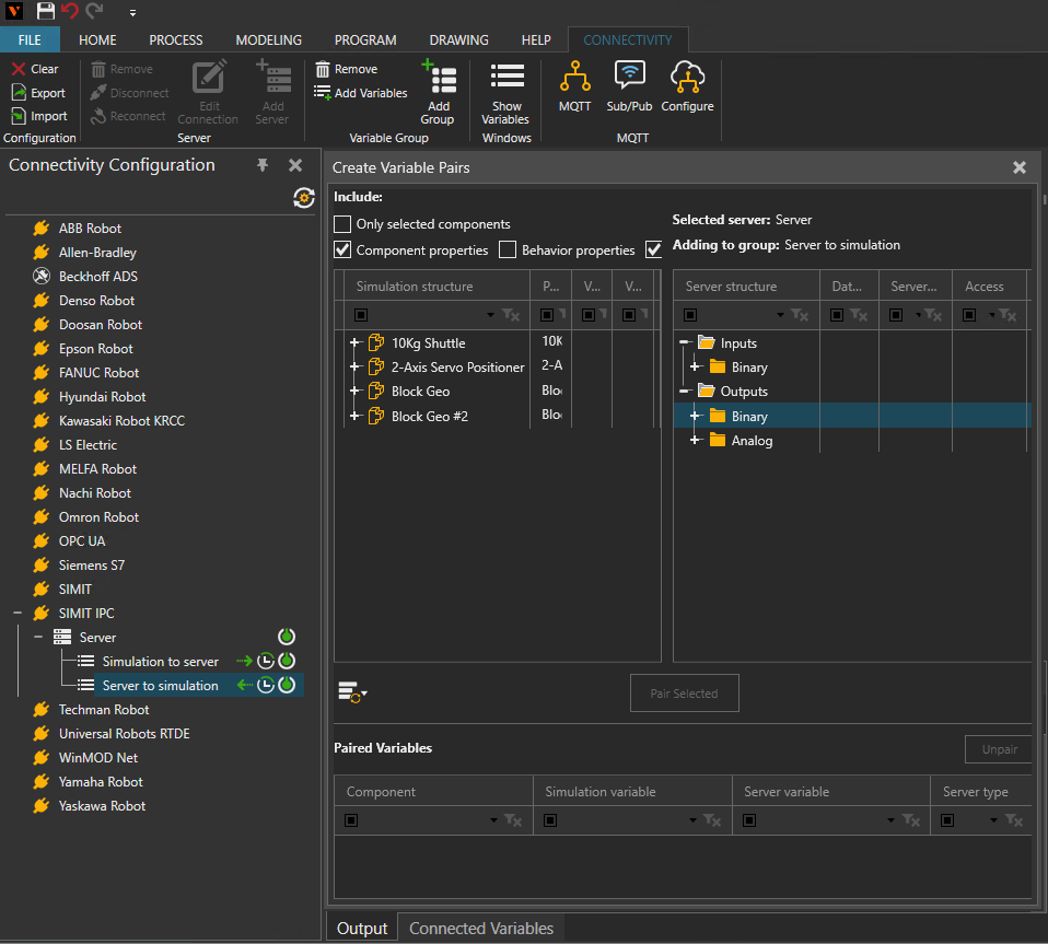
- Run the simulation. If Simulation Control (RCI) is connected, starting, stopping and resetting the simulation in Visual Components also runs, stops and resets the SIMIT SP simulation:
Note: Always connect in Visual Components before starting the SIMIT SP simulation.- The coupling must already be waiting when SIMIT SP starts the simulation.
- While a SIMIT simulation is open, Visual Components cannot connect, stop or reset.
- The user should close the SIMIT simulation first.
- Additional options:
- Simulate to start the exchange of data. In the Connected Variables panel, you can use the Prepared value column to set values for testing.
- Synchronize the simulation speed (optional).
- To make SIMIT follow the simulation speed of Visual Components (Visual Components acts as the clock generator):
- In the SIMIT coupling properties, keep Isochronous selected.
- In the SIMIT IPC plugin Properties panel, set Operating Mode to Isochronous. You can change this setting only while no SIMIT simulation is open.
- Connect and run the simulation as described above.
- When Visual Components runs in virtual time, SIMIT runs at maximum speed.
Capabilities
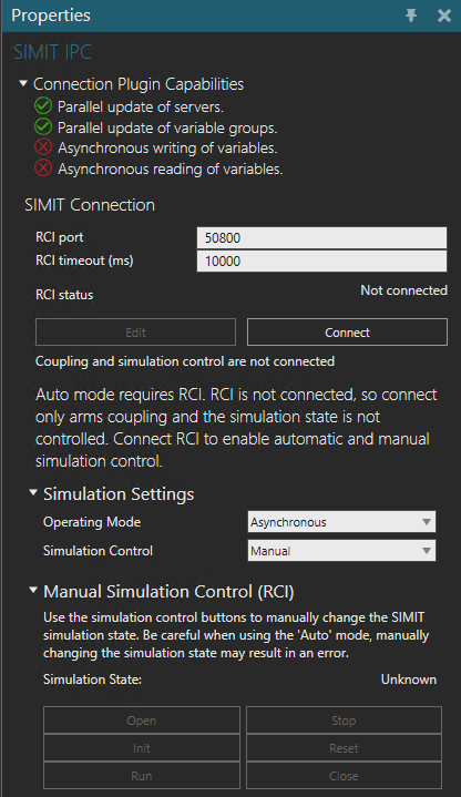
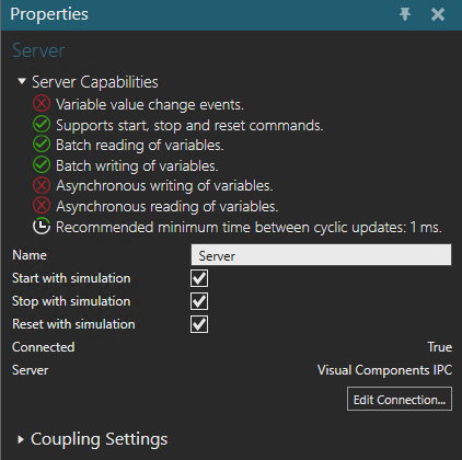
You can verify the capabilities of the SIMIT IPC plugin and subsequent server connections in the Properties panel.
Plugin
- In the Connectivity Configuration panel, select SIMIT IPC.
- In the Properties panel, expand Connection Plugin Capabilities.
Server
- In the Connectivity Configuration panel, expand SIMIT IPC, and then select an active server connection.
- In the Properties panel, expand Server Capabilities.
Connection Settings
- A SIMIT IPC connection does not use an IP address or port for signal exchange. Visual Components and SIMIT must run on the same PC.
- Each server connection selects a coupling with the Simulation project and Simulation project part fields in the Edit Connection dialog. These must match the Simulation Project and Simulation Project Part properties of the coupling in SIMIT. Leave both empty when the project has one coupling.
- The following settings apply to the SIMIT IPC plugin as a whole and are shared by all its servers. To view them, select SIMIT IPC in the Connectivity Configuration panel.
Setting Options Default Description RCI Port Port number 50800 Port of SIMIT simulation control (RCI). Change it only if SIMIT uses a different port. RCI timeout (ms) Milliseconds 10000 Timeout for connecting to RCI and for each RCI command. RCI status Connected, Not connected – - State of the connection to SIMIT simulation control.
- Use Connect / Disconnect to change it.
- To change the port or timeout while connected, click Edit.
Operating Mode Asynchronous, Synchronous, Isochronous Asynchronous - Mode in which SIMIT runs the simulation when it is initialized or run from Visual Components.
- Choose Isochronous to make SIMIT follow the Visual Components simulation speed.
- Can be changed only while no SIMIT simulation is open.
Simulation Control Manual, Auto Manual - Manual: connecting only arms the coupling, and you start SIMIT with the buttons under Manual Simulation Control (RCI) or in SIMIT.
- Auto: connecting also opens and initializes the SIMIT simulation, and disconnecting closes it. Auto is available only while RCI is connected.
- Under Manual Simulation Control (RCI), Simulation State shows the state of the SIMIT simulation: No Simulation, Loaded, Stopped, Running or Unknown.
- The buttons Open, Init, Run, Stop, Reset and Close change the state. Only the button that is valid for the current state is enabled.
- In the server Properties panel, under Coupling Settings, select Show Coupling Logs to show detailed coupling messages in the Output panel. This is useful for troubleshooting. The setting takes effect the next time you connect.
Error handling
- "Cannot connect while a SIMIT simulation is open (state: …)":
- You tried to connect while a SIMIT simulation was open.
- Stop, reset and close the SIMIT simulation (in SIMIT, or with the buttons under Manual Simulation Control (RCI)), and then connect again.
- "SIMIT Application not available (RCI)…":
- Simulation control could not connect.
- Check that SIMIT is running, and that the RCI port matches SIMIT.
- Signal exchange through the coupling still works; only simulation control is unavailable.
- "Cannot Init the SIMIT simulation. Please check if project is opened and saved…":
- Make sure that the SIMIT project is open and saved and then try again.
- SIMIT cannot initialize the simulation (gateway error at Init1):
- The coupling has no signals. Define at least one signal and save the project.
- The SIMIT simulation ends:
- Visual Components stays connected, and the coupling waits for the next SIMIT simulation start automatically.
- Until then, the exchange of data stops.
- The connection to SIMIT simulation control is lost, for example after SIMIT is restarted:
- RCI status can still show Connected, while Simulation State shows Unknown.
- Click Disconnect and then Connect.
- "The coupling host process exited unexpectedly. Respawning and re-arming.":
- The plugin restarts the coupling automatically. No action is needed.
- "Failed to arm the SIMIT coupling (out-of-process coupling host)…":
- Check that SIMIT is installed on the same PC, and that the Visual Components installation is complete.
- A variable pair shows an error after you edit signals in SIMIT:
- Renaming a signal, or changing its data type, breaks its pairs. Pair the variable again.
- To diagnose problems, enable Show Coupling Logs before connecting and check the Output panel.
Limitations
- Visual Components and SIMIT must run on the same PC.
- Only signals defined in the Visual Components IPC coupling are accessible. Supported types: Binary, Integer, Analog.
- Visual Components can read only inputs (From SIMIT) and write only outputs (To SIMIT).
- Signals are available only after SIMIT has initialized the simulation.
- Visual Components must be connected before the SIMIT simulation starts.
- With several couplings, use Manual simulation control.
- Values are polled. The plugin does not provide value change events.
- Renaming a signal in SIMIT breaks its variable pairs. Renaming the coupling in the SIMIT project tree does not.
- Signal lists exported to CSV do not contain initial values or descriptions.
Compatibility
- The SIMIT IPC plugin was developed using the SIMIT external coupling API and the SIMIT Remote Control Interface.
- It supports and was tested with SIMIT V10.3 and later.
- For a connection to SIMIT on another PC, use the older SIMIT plugin. It is deprecated as of SIMIT V11.3.
Performance
- Values are polled; the plugin does not provide value change events. Use the cyclic update mode for variable groups in both directions.
- Choose a cycle interval that is the same as or longer than the Time slice of the Visual Components IPC coupling in SIMIT.
- Set the coupling time slice to a reasonable value. There is no point in updating the coupling faster than the SIMIT charts that provide or use the data.
- Signal changes shorter than the variable group's cycle interval can be missed. If Visual Components writes a signal several times within one SIMIT cycle, only the last value reaches SIMIT.
- In Isochronous mode, SIMIT waits for the coupling in every cycle so that it follows the Visual Components speed.
Supported data types
The SIMIT IPC plugin supports access to the Binary, Integer and Analog signals of the Visual Components IPC coupling.
| SIMIT coupling signal type | .NET Type |
| Binary | System.Boolean |
| Integer | System.Int64 |
| Analog | System.Double |
Other Notes
- Migrating from the SIMIT plugin:
- Add the Visual Components IPC coupling to your SIMIT project.
- Recreate the signals (for example with Import signals).
- Connect your SIMIT charts to the new coupling signals.
- In Visual Components, add a SIMIT IPC server and pair the variables again.
- The Visual Components coupling, used by the SIMIT plugin, and the Visual Components IPC coupling can be installed in SIMIT at the same time.