Logic Modeling (Early Access)
Note: Logic Modeling is still in Early Access. Logic Modeling features created during Early Access, including plugins and integrations, may not be fully compatible with future versions of Visual Components.
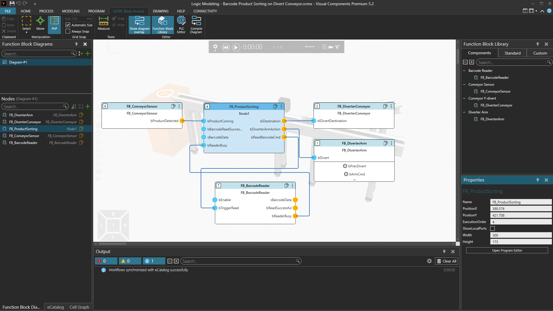
Overview
Logic Modeling enables you to create, test, and execute PLC-style logic directly within Visual Components. It combines simulation and control logic in a single environment, allowing you to develop and validate automation behavior without switching between separate simulation and PLC engineering tools.
Logic Modeling is based on the IEC 61131-3 standard and supports Structured Text (ST) programming together with visual Function Block Diagrams (FBDs). Logic can be developed and tested as part of a simulation model and later connected to external PLC systems when required.
Logic Modeling availability
Logic Modeling Runtime allows layouts with Logic models to be run and reused in all Visual Components 5.2 products.
To create or edit Logic Models, the Logic Modeling Add-on must be enabled. The Logic Modeling Add-on is available in the following products:
| Product | Logic Modeling Runtime | Logic Modeling Add-on |
| Visual Components Essential 5.2 |  Run / Reuse |
 Not Available |
| Visual Components Robotics OLP 5.2 | Run / Reuse |
Not Available |
| Visual Components Arc OLP 5.2 | Run / Reuse |
Not Available |
| Visual Components Digital Twin 5.2 | Run / Reuse |
Not Available |
| Visual Components Professional 5.2 | Run / Reuse |
Available |
| Visual Components Premium 5.2 | Run / Reuse |
Available |
| Visual Components Professional OLP 5.2 | Run / Reuse |
Available |
| Visual Components Premium OLP 5.2 | Run / Reuse |
Available |
To enable the Logic Modeling Add-on:
- Select File > Options > Add-on.
- Locate Logic Modeling Add-on.
- Select Activate and enter your Logic Modeling license information.
- Select OK.
- Restart the application.
- After restarting the application all the functions in the LOGIC (Early Access) tab are available.
Main concepts
Logic Modeling consists of several key elements:
Function Block Diagrams
Function Block Diagrams (FBDs) are the main workspace for creating layout-level logic. A diagram contains function blocks, variable pairs, and connections that define how data flows between different parts of the system. See, Function Block Diagrams.
Function Blocks
Function blocks are reusable logic modules that perform specific tasks. Logic Modeling supports several types of function blocks:
- Component Function Blocks provide access to component properties, signals, and other simulation data.
- Custom Function Blocks allow you to create reusable logic that is independent of a specific component.
- Standard Function Blocks provide common mathematical, logical, and comparison operations.
See, Function Blocks.
Structured Text
Structured Text (ST) is used to implement the logic executed by function blocks. It is an IEC 61131-3 programming language commonly used in PLC applications. Logic programs can be edited and validated directly in Visual Components.
Simulation PLCs and Variable Pairs
Simulation PLCs (SimPLCs) provide a mechanism for storing and exchanging data. They contain Variable Pairs, which can be used to share information between diagrams or communicate with external PLCs and other systems. See, PLC Editor.
Workflow
A typical Logic Modeling workflow consists of the following steps:
- Create one or more Function Block Diagrams.
- Add function blocks to the diagrams.
- Define the required logic using Structured Text and connections between blocks.
- Compile the diagrams.
- Run the simulation and validate the behavior.
- Optionally connect the simulation to external PLC systems.
User interface
Most Logic Modeling functionality is available from the Logic (Early Access) tab, where you can create and manage Function Block Diagrams, access the Function Block Library, open the PLC Editor, and compile logic diagrams.