Point control
NOTE: This topic is only applicable to the following Robotics OLP products:
- Visual Components Premium OLP
- Visual Components Professional OLP
- Visual Components Robotics OLP
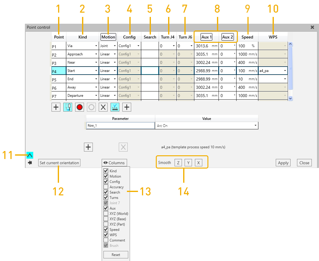
Point control window opens from Test path section in Path setup. In the point control user interface, all the points in the path can be modified. The parameters to modify are: Kind, Motion type, robot Configuration, Search assigned to the point (memory slot value of search), Turn of robot joint J6 (also J4 for some robots), Auxiliary axis values, Speed and WPS.
To modify the parameters, select the points to be modified, modify the values and click Apply.
Note: you can modify parameters for multiple points at the same time by multiselecting the points, modifying the value at one point and pressing ENTER or by clicking another field.
Tip: multiselect can be done by Ctrl + clicking OR Shift + clicking OR clicking the first point -> “painting” the points by keeping the mouse button down -> releasing at the last point. To select all the points, click one point and Ctrl + A.
|
No. |
Name |
Description |
|
1. |
Point |
Shows all the points in the weld path |
|
2. |
Kind |
Denotes if the point is an approach, via start point and so on |
|
3. |
Motion |
Denotes if the point is linear or point to point |
|
4. |
Config |
Denotes the configuration of the robot |
|
5. |
Search |
The memory location for search is inserted over here to link the weld path to search function |
|
6. |
Turn J4 |
Specify the turn for J4 joint of the robot |
|
7. |
Turn J6 |
Specify the turn for J6 joint of the robot |
|
8. |
Aux |
Specifies the auxiliary axes (Robot positioner, Workpiece positioner) joint values. |
|
9. |
Speed |
Specifies speed values |
|
10. |
WPS |
Apply welding parameter template to the point |
|
11. |
WPS view |
Click on this arrow to view the welding parameters for selected template. Described more below |
|
12. |
Set current orientation |
Change the robot orientation for certain or multiple points and click on set current orientation. |
|
13. |
Columns |
Select the needed columns to be visible in Point control window |
|
14. |
Smooth XYZ |
Smoothens the tool path around Z, Y and/or X axis for the selected points in the path. To smoothen the path, multiselect the points and click Z, Y and/or X. |
Comment: Insert comments for each of the points in the weld path.
Note: operators +, -, * and / works in the fields
Aux axis smooth and set current value for Aux
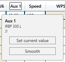
When hovering on Aux column header with mouse cursor, pop-up window is shown.
There are two buttons in this pop-up window:
-
Set current value:
Saves the current value of the auxiliary/external joint to the points selected in the
Point control window.
-
Smooth external axes:
Allows smooth transition between points in the path by smoothening the motion of the auxiliary axis. Select all the points in the path and click on the Aux1(if you wish to smoothen e.g. joint values for robot positioner).
NOTE: The sequence is robot positioner followed by Workpiece positioner. For example, if the layout has a linear track and a 2-axis Workpiece positioner; Aux1 represents joint1 of track, Aux2 & Aux3 represents joint 1 and joint 2 of workpiece positioner respectively.
WPS view
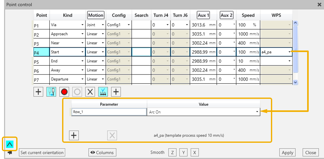
The WPS view allows to:
- See the WPS parameters for Process start, Process end or Process points.
- Edit (add/delete/modify) the parameters from this view.
- See the template process speed.
Hit apply to save any changes you make.
Point Coordinate Visibility
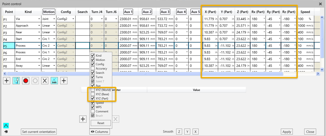
You can enable the XYZ columns to view the Point wr.t World or Base or Part coordinates.
Circularize function
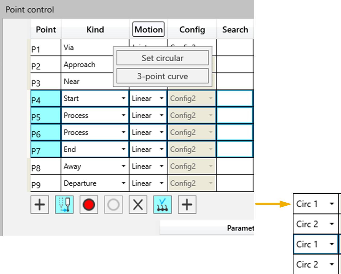
Set circular
If the points in the path are Linear and you need to change it to circular move points, then use the Set circular function. Multiselect the points that are needed to be converted to Circ Points and choose the Set Circular option.
3-point curve
Select 3 points. Click on 3-point curve. Hit apply. A curve will be generated using the first and last point.
Re-sequence points
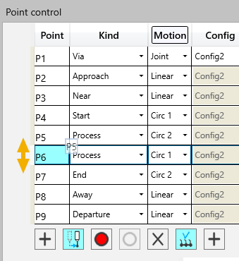
You can re-sequence points by dragging and dropping the point as needed.