Setup tab
NOTE: This topic is only applicable to the following Robotics OLP products:
- Visual Components Premium OLP
- Visual Components Professional OLP
- Visual Components Robotics OLP
Cell setup: Active components in robot cell
- Robot as WPP: robot is used as a workpiece positioner in the setup
-
Run setup: Sets the categories and properties for the components
(This need to be done after the cell is modelled)
Multi-robot:
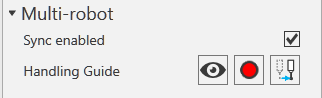
Checking the Sync enabled option allows to use 2 or more robots in synchronous mode. The handling guide buttons allow to hide, move and save the handling guide position.
- Visibility: Set the visibility on or off for the guide
- Touch up: Touch up a new default location for the Handling guide
- Jump to: Click on this to move the handling guide to its default location
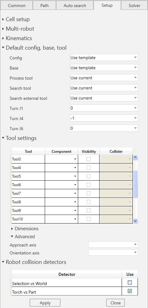
Default config, base,tool: Set the default Config, Base, Process tool and Search tool.
- Default Turn value: Default turn values can be set for the J1/J4/J6 axes of the robot if needed. This could be used for instance when it is known that certain turn value works best for the paths given the complexity of the cabling.
Tool settings: If the layout consists of multiple welding torches, use this setting to view needed welding torch based on the tool number that you have selected while creating paths.
E.g., From the component dropdown menu, assign the correct CAD geometry to the correct tool index.
-
Dimensions: When using touch sensing with nozzle the dimensions for the nozzle should be set into these fields. The description of measurements provided below.

a = Wire length from gas nozzle
b = Wire diameter
c = Torch diameter
d = Shoulder distance
e = Shoulder diameter
-
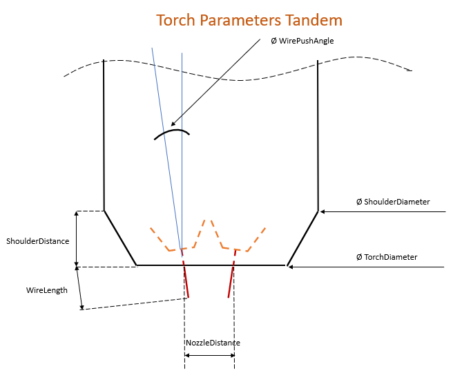
Tandem dimensions: When using touch sensing with tandem torch, the dimensions of the tandem torch nozzle need to be set in these fields.
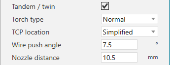
WirePushAngle = Wire angle inside the nozzle
NozzleDistance = Distance between the tips of the nozzles
Torch type = ["Normal", "Rotated"] The way the wires are aligned, Normal being wires in line
TCP location = ["Aligned with Wire", "Simplified"]
TCP at the end of each wire aligned with wire OR only one TCP for the tandem, located in between the wires, not aligned with wire (meaning TCP Z-axis is pointing directly out from nozzle).
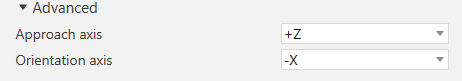
Advanced: Set the default Approach and orientation axis for the tool from here.
Robot collision detectors: The enabled detectors will be used by the path checker described in Path check. If WP is checked, the workpieces of the checked weld and search statements are automatically added to the B list of the detector.