Product Type Editor
The Product Type Editor panel shows the product types and the assemblies created for the layout. The panel allows you to add and edit types and assemblies of products and arrange them to flow groups. You can also define properties for the product types and assemblies.
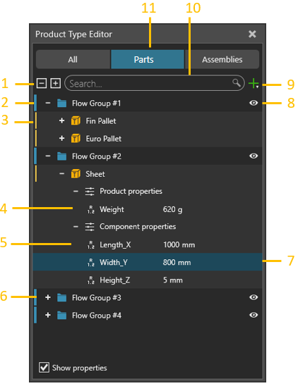
| 1. | Expand/Collapse Flow Groups and Product Types |
| 2. | Flow Group |
| 3. | Product Type |
| 4. | Properties of a Product |
| 5. | Properties Associated with Component |
| 6. | Collapsed Flow Groups |
| 7. | Selected Property |
| 8. | Visibility of Flow Group in Process Flow Editor Panel |
| 9. | Add Product Type or Flow Group |
| 10. | Search Box for Names of Properties, Product Types and Flow Groups |
| 11. | Select if Product Types or Assemblies are shown |
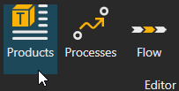
Access
To access the Product type editor:
- Click the Process tab.
- In Editor group, Click Products command
- The Product Type Editor panel appears on the left.
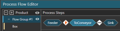
Flow Groups
Every product type belongs to a flow group. A flow group can have one or more products.
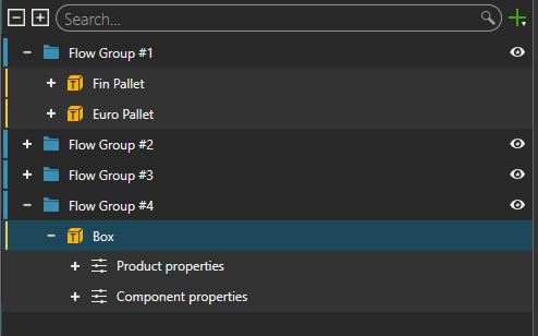
A flow group controls the flow of its products from one process to another. In all cases, products of the same flow group have the same flow. For example, different types of boxes could belong to one flow group and go through the same process steps.
Product Types
A product type is the definition of what you want to manufacture in the 3D world. That is, you can make any type of product.
Product type has three kind of properties: Default, Component and Product properties. Default properties cannot be changed but their values must be defined. Component and product properties are optional and they are added manually. You can edit, copy, paste and move them between different product types and property groups.
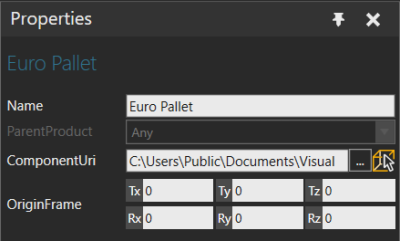
Default Properties
Every product type has a default set of properties.
- Name is the name of the product.
- ParentProduct indicates if the product inherits properties from another product.
- ComponentUri is a component associated with the product. You have the option to use the VCID or URI of a component, or to select the component in the 3D world. When using the VCID of a component, type "vcid:" followed by the VCID, and then press ENTER. Any properties associated with a component are used as the default component properties unless overwritten using the Component Properties as described below.
- OriginFrame defines the origin of the product in relation to an associated component.
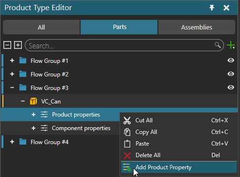
Product Properties
A product has its own set of properties. Product properties can be used to maintain the information throughout the production, while the associated component with its properties is changed due to an increase in the production phase.
A product supports the following property types:
-
Double (Real type number)
-
String (text)
-
Int32 (regular Integer number)
-
Boolean value (True or False)
-
Vector
-
Matrix
-
URI
-
Material
-
Custom type implemented using API
Be aware that product properties are not listed in the Properties panel of the selected dynamic component. However, they can be accessed with statements of a process routine or APIs.
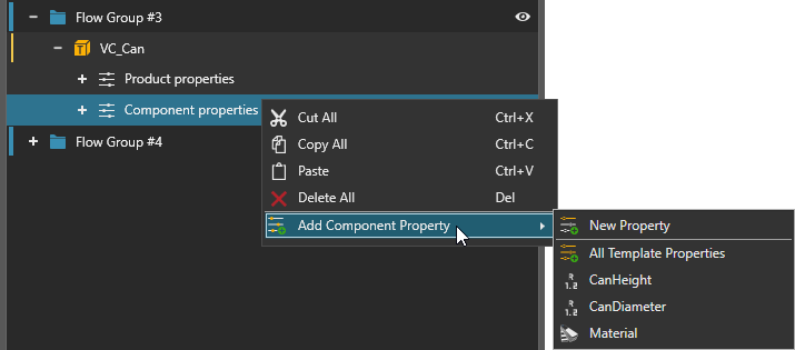
Component Properties
A product has its own set of properties to associate with a component. You can create new properties which will be added upon creation of the product instance to the dynamic component or add properties from an associated component to define their default values.
Added / assigned upon creation of the product instance.
Be aware that a product is not a component. That is, they are two separate objects. Removing the association between a product and component does not remove the component properties of a product. In this context, think of a product type as a template for making new parts during a simulation. Associating a component with a product and adding one or more of its properties is a quick way to define or prototype a new product. Editing the properties of the component, however, have no effect on the component properties of a product.
Product Creator
A Product Creator is a behavior that allows a component to create product instances from product types during simulation. Thus, you can use a component having this behavior in order to create product instances in simulation defined in Product Type Editor panel. From eCatalog’s Visual Components Public Models, you can use Source Process component as a stationary feeder or Product Feeder component as an inline feeder.

A Product Creator can create products using one of several modes.
-
Single creates product of a single type at a given interval.
-
Batch creates one or more product types in a specific order. Every entry in a batch represents a product type, its quantity, and the interval for creating the needed amount. You have the option to create a one batch or several at a given interval.
-
Table allows you to import an Excel file that defines which products to create at specified times
-
Distribution chooses product type to create based on a weighted probability.
Assemblies
Assemblies are hierarchical structures of Assembly Steps. Each Assembly Step represents one logical step in the product’s hierarchy that can be assembled or disassembled.
Each Assembly Step has a location compared to its parent step, and each step has its own Step properties.
Every step contains one or more Assembly Slots for the Product Types. The slot configuration is done in the Assembly Editor.
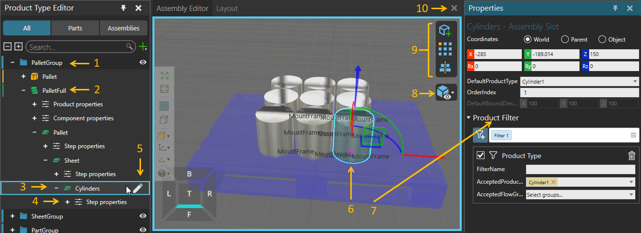
- Flow group of the Assembly Product Type.
- Assembly Product Type. Assemblies can be handled as any other Product Types with the PM statements.
- Selected Assembly Step. This step represents a group of cylinders in the pallet assembly.
- Step properties of the selected Assembly Step. Step properties can be read with the PM statements.
- Open the Assembly Editor icon for the selected step. The icon is only shown when a cursor is placed on the Assembly Step. Assembly Editor opens as a new 3D environment panel in which users can define the number of slots, their location, and the Product Type for the slots.
- Selected Assembly Slot in the Assembly Editor. Each slot can be manipulated freely using tools such as Select, Move, Measure, Snap, Align, ... Also, selected slots can be copy-pasted as well. By default, the slot is visualized with a cube geometry.
- Assembly Slot properties:
- OrderIndex defines the product assembling and disassembling order when having multiple slots. The placing order starts from the lowest value, and the picking order starts from the highest value.
- AcceptAllProductTypes, AcceptProductTypes and AcceptFlowGroups are used to filter the Product Instances accepted to the slot when the assembly is constructed during the simulation. Product Filtering linked below, is used to filter the product Instances accepted to the slot when the assembly is constructed during the simulation.
- DefaultProductType defines the default Product Type created to the slot when the step or the assembly is initially created.
- DefaultsBoundsDimensions defines the default dimensions of the slot geometry. These dimensions will be overridden if the DefaultProductType is selected.
- Assembly Visualization toolbar. The selected step is always visualized, but the other steps can be shown with transparent blue material.
- Slot adding and slot centering tools. Slots can be created individually, or they can be created as a pattern. When creating a pattern, a template pattern can be used. It is also possible to utilize already existing patterns from other Assembly Steps and Assemblies. With the slot center tool, the slot locations can be centered to the assembly step origin.
- Close the Assembly Editor
- Product Filtering.