Home
The Layout view allows you to build layouts in the 3D world using components.
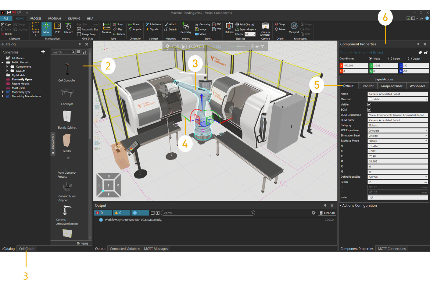
| 1. | Cell Graph Panel |
| 2. | eCatalog Panel |
| 3. | Selected Component |
| 4. | Manipulator |
| 5. | Property Tabs |
| 6. | Properties Panel |
Access
To access the Layout view:
- Click the Home tab.
Panels
The Layout view shows, by default, the following panels:
- eCatalog for browsing connected sources of files and adding them to a layout.
- Cell Graph for listing, selecting and editing components in a layout.
- Properties for reading and writing properties of selected components in a layout.
Context
The context of the Layout view is layout configuration.
You can:
- Open, save and create new layouts.
- Add, select, edit and manipulate components.
- Run and record simulations as 3D PDFs.
- Visualize and render components in different environment settings.
- Export components and layouts as images and CAD files.
Commands
By default, the following commands are shown in the Ribbon when you click the Home tab.
| Name | Description |
| Copy | Copies the current selection to the clipboard. |
| Paste | Adds the contents of clipboard to active area or field of workspace depending on data type. |
| Delete | Deletes the current selection. |
| Group | Adds selected components to a new group. See Grouping components. |
| Ungroup | Removes selected components from one or more groups, and then deletes those groups. |
| Select | Allows for direct and indirect selection of components in the 3D world using listed commands.
Rectangular selection Free-form selection Select all Invert selection |
| Move (Manipulation) | Allows a selected component to be moved along an axis or plane, rotated around an axis, and snapped and aligned to a point in 3D world. |
| PnP | Allows the pointer to plug selected components into other components to form physical connections. See Plugging in components.
Note: A selected component must have an interface, otherwise it cannot be plugged into any component. Other components must have compatible interfaces, otherwise selected components will not plug into them. Components that are plugged into one another may or may not be attached to one another. |
| Interact | Allows the pointer to jog joints and other interactive properties of components in one or more degrees of freedom in the 3D world. See Interacting with parts of components. |
| Size | Defines the interval for snapping a selected object along an axis or plane when using the manipulator. |
| Automatic Size | Turns on/off the automatic calculation of intervals for snapping a selected component along an axis or plane when using the manipulator. |
| Always Snap | Turns on/off the automatic snapping of a selected component along an axis or plane at intervals when using the manipulator. |
| Measure | Measures the distance and/or angle between two points in 3D world. Additional options are displayed in a task pane. See Measuring components.
Mode Settings Snap Type Tip: The results of a measurement are sent to Output panel. |
| Snap (Tools) | Allows a selected component to be snapped to a location in 3D world by using one to three points. Additional options are displayed in a task pane. See Snapping components.
Mode Settings Snap Type |
| Align | Aligns a selected component using two points. Additional options are displayed in a task pane. See Aligning components.
Settings Snap Type |
| Pattern | Creates multiple copies of a selected component using a linear or angular arrangement. Additional options are displayed in a task pane. See Creating a pattern of components.
Mode
Coordinate System
Pattern Along (Linear Pattern) Linear Step (Linear Pattern) Pattern Around (Angular Pattern) Offset Along (Angular Pattern) Offset Distance (Angular Pattern) Angular Step (Angular Pattern) Count Connect Interfaces Apply |
| Linear (Dimension) | Creates a dimension that measures the linear distance between selected references in the 3D world. Additional options are displayed in a task pane.
Snap Type |
| Angular (Dimension) | Creates a dimension that measures the angle between two selected edges in the 3D world. |
|
Interfaces |
Allows components to be remotely connected in the 3D world using abstract interfaces. Additional options are displayed in a task pane. See Connect Interfaces. Component Interface Connections Display Network Map Show Connection Lines Show Non-abstract Interfaces Note: By default, interface editors (nodes) for components are not displayed unless they have two matching interfaces with the selection. You can change this by editing "interfacesNodeVisibilityThreshold" in the app.config file. |
|
Signals |
Allows signals of components and I/O of robot to be connected to one another in 3D world. Additional options are displayed in a task pane. See Connect Signals. Component Signal Connections Tip: For inputs and outputs of robot, we recommend using signals 100 onward for new signal connections and actions. This helps avoid conflict with predefined actions for robots. Display Network Map Show Connection Lines Enable Signal Toggling |
| Attach | Attaches a selected component to a node of another component, thereby forming a new parent-child hierarchy in the layout. See Attaching components. |
| Detach | Detaches a selected component from a node of another component, thereby removing a parent-child hierarchy from the layout. |
| (Import) Geometry | Imports the geometry of a supported file. Additional options are displayed in a task pane, see Import Model Settings. |
| (Export) Geometry | Exports the geometry of all or selected components to a new supported file. See Exporting geometry of components and Exporting geometry of layouts. |
| Image | Allows the 3D world view within a border to be captured, and then exported as a new file or copied to the clipboard. Additional options are displayed in a task pane. See Exporting simulation as image.
Resolution File Format Render mode Export |
| Video | Records simulation as a video. See Recording simulation as video. |
| Record simulation as a 3D PDF. See Recording simulation as 3D PDF. | |
| Statistics | Launches a dashboard for configuring charts and reporting data collected during a simulation. See Reporting statistics. |
|
Print Chart(s) |
Prints all or selected charts in Statistics dashboard. |
|
Export Graph |
Exports all charts in Statistics dashboard to either a CSV or Excel file. Export to Excel Export to CSV |
|
Interval |
Defines the global sampling rate for reporting Statistics behavior properties. This includes cumulative, interval and state-based statistics. The default is to report data every 60 seconds during simulation. |
|
Camera Animator |
Defines camera movements for active layout in 3D world. Additional options are displayed in a task pane. See Animating camera movements. Simulation Time Relative Time View Time Arc + Trashcan |
| Snap (Origin) | Allows the point of origin in selected component to be snapped to a location in 3D world by using one to three points. Additional options are displayed in a task pane. See Editing origin of components.
Mode Settings Snap Type Apply |
| (Origin) Move | Allows the point of origin in active component to be moved in 3D world. Additional options are displayed in a task pane. See Editing origin of components.
Apply |
| Viewport | Opens the FactoryLens viewport. Only visible if FactoryLens add-on is enabled. See FactoryLens. |
| Image (FactoryLens) | Only visible if FactoryLens add-on is enabled. Allows the FactoryLens viewport to be captured and then exported as a new file. Additional options are displayed in a task pane. See FactoryLens. Resolution Width Height Maintain Aspect Ratio File Format |
| Video (FactoryLens) | Only visible if FactoryLens add-on is enabled. Allows the FactoryLens viewport to be captured and exported as a video. Additional options are displayed in a task pane. See FactoryLens. Resolution Frame rate Video codec |
| USD | Allows exporting the Layout to USD file format. Only visible if FactoryLens add-on is enabled. See FactoryLens. |
| Restore Windows | Restores the workspace of current view to its default setting. See Restoring windows |
| Show | Displays a list of panels that can be shown/hidden from the current view of workspace. |