Logic Program Editor
Note: Logic Modeling is still in Early Access. Logic Modeling features created during Early Access, including plugins and integrations, may not be fully compatible with future versions of Visual Components.
The Logic Program Editor is used to create and modify Logic Programs. A Logic Program defines the interface and functionality of a function block through ports and Structured Text (ST) code.
Use the Logic Program Editor to configure ports, link ports to objects in the simulation, and define the functionality of the function block using Structured Text.
Opening the Logic Program Editor
The Program Editor can be opened from the Logic tab or from the properties of a Function Block (Early Access) behavior.
To open the Program Editor from the Logic tab, select the Function Block that you want to edit, and then select Program Editor.
To open the Program Editor from a Function Block behavior, open the Modeling tab, select the Function Block behavior, and then select Open Program Editor in the Properties panel.
Adding and configuring ports
Ports define how data is used by the Logic Program and exchanged with other elements in Logic Modeling.
To add and configure a port:
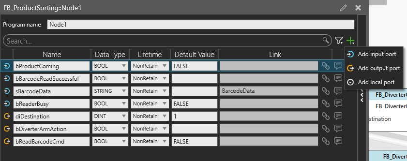
- In the Program Editor, select + to add a port.
- Select the port direction: Input, Output, or Local. For more information about port types, see Function Blocks.
- Enter a Name for the port.
- Select the required Data Type.
- Configure the Lifetime, if required.
- Configure the Default Value, if required.
If the port needs to exchange data with an object in the simulation, you can link the port to a component property, behavior property, signal, or signal map. For more information, see Linking ports.
The configured port is added to the Structured Text code and can be used as a variable in the Logic Program.
Linking ports
Ports can optionally be linked to objects in the simulation. Linking a port synchronizes the port value with the linked object, allowing the Logic Program to read values from or modify values in the simulation. Ports can be linked to component properties, signal behaviors, signal map ports, and behavior properties. The available objects depend on the port type.
To link a port:
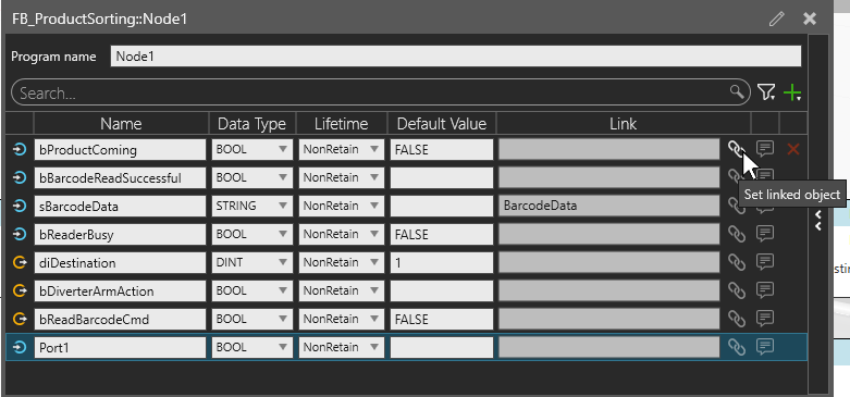
- In the Program Editor, select + to add a port.
- Select Set linked object for the port that you want to configure.
- From Link type, select one of the following:
- Property: Select the component property from Property.
- Behavior property: Select the behavior from Behavior, and then select its property from Property.
- Signal: Select the signal from Signal.
- Signal map: Select the signal map from Signal map, and then specify the Port index.
Editing Structured Text
Structured Text (ST) defines the logic executed by the function block.
To edit the Structured Text code, open the ST Code editor by clicking the  from the right side Logic Program Editor.
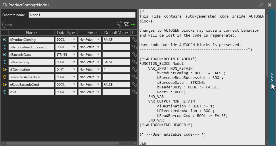
Ports configured in the Logic Program are available as variables in the Structured Text code. The port declarations are added to the auto generated section of the code.
Add your logic to the user-editable code section. Changes made in the Logic Program Editor are saved automatically.
Note: Do not modify the auto generated section of the ST code.